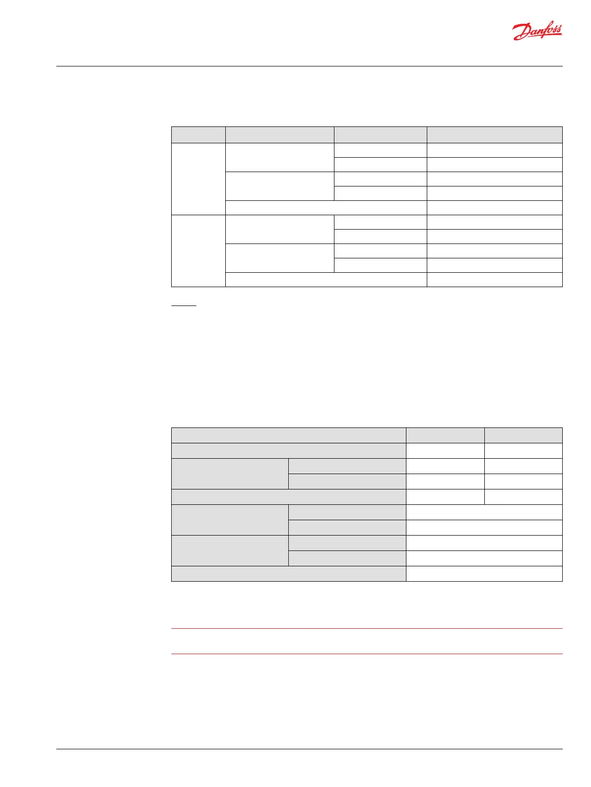
Formulas to calculate start and end input command
Control type Input command (mA) % displacement
All sizes (mA)
D1
Start input command from 100%
480 ± 10
from y% max.
(1 - V
gy
/V
gmax
) x 1110 + 480
End input command at 0 %
1590 ± 130
at x % min.
(1 - V
gx
/V
gmax
) x 1110 + 480
Max allowed current
1800
D2
Start input command from 100%
240 ± 5
from y% max.
(1 - V
gy
/V
gmax
) x 570 + 240
End input command at 0 %
810 ± 67
at x % min.
(1 - V
gx
/V
gmax
) x 570 + 240
Max allowed current
920
Where:
V
gmax
Maximum, theoretic possible motor displacement per revision (cm
3
/rev)
V
gx
Minimum displacement setting of desired unit (cm
3
/rev)
V
gy
Maximum displacement setting of desired unit (cm
3
/rev)
x Minimum displacement (%)
y Maximum displacement (%)
Proportional solenoid data C1
Description 12 V 24 V
Maximum current
1800 mA 920 mA
Nominal coil resistance @ 20 °C [68 °F]
3.66 Ω 14.20 Ω
@ 80 °C [176 °F]
4.52 Ω 17.52 Ω
Inductance
33 mH 140 mH
PWM Range
70-200 Hz
Frequency (preferred)
*
100 Hz
IP Rating IEC 60 529
IP 67
DIN 40 050, part 9
IP 69K with mating connector
Connector color
Black
*
PWM signal required for optimum control performance.
Warning
Zero degree capability results in a high risk of overspeed and drops in efficiency if the motor operates
between 0–20% displacement.
Technical Information
H1 Bent Axis Variable Displacement Motors, Size 060/080/110/160/210/250
Controls – nomenclature, description
©
Danfoss | December 2016 11037153 | BC00000043en-US1103 | 45

 Loading...


