H1 pumps are limited in mechanical orificing combinations. Mechanical servo orifices are to be used only
for fail-safe return to neutral in the event of an electrical failure.
Typical response times shown below at the following conditions:
∆p
250 bar [3626 psi]
Viscosity and temperature
30 mm²/s [141 SUS] and 50 °C [122 °F]
Charge pressure
20 bar [290 psi]
Speed
1800 min
-1
(rpm)
Response time, MDC 069/078
Code
Orifice description (mm) Stroking direction (sec)
P A B
Tank (A+B) Neutral to full flow Full flow to neutral
C3
– – – – 0.4 0.5
C6
– – – 1 1.4 1.1
C7
– – – 1.3 0.9 0.8
C8
0.8 – – 0.6 4.2 3.1
C9
1 – – 0.6 3.9 2.9
D1
1 – – 0.8 2.5 1.9
D2
1.3 – – 0.8 2.2 1.7
D3
1.3 – – 1 1.6 1.2
D4
1.3 1.3 1.3 1 1.9 1.5
D5
0.6 0.8 0.8 0.6 7.5 4.4
D6
1.3 – – 1.3 1.9 1.5
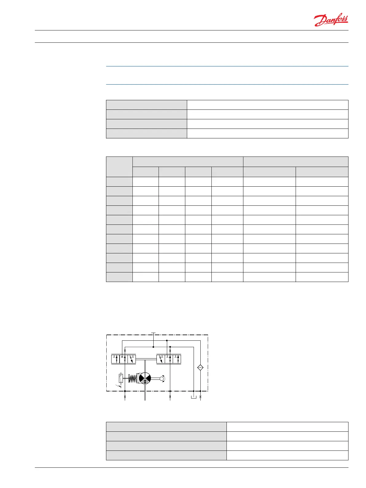
Neutral Start Switch (NSS)
The Neutral Start Switch (NSS) contains an electrical switch that provides a signal of whether the control
is in neutral. The signal in neutral is Normally Closed (NC).
Neutral Start Switch schematic
Neutral Start Switch data
Max. continuous current with switching
8.4 A
Max. continuous current without switching
20 A
Max. voltage
36 V
DC
Electrical protection class
IP67 / IP69K with mating connector
Technical Information H1 Axial Piston Single Pumps, Size 069/078
Control options
11062169 • Rev 0700 • November 2015 21

 Loading...


