Charge pump
Charge pump sizing/selection
In most applications a general guideline is that the charge pump displacement should be at least 10% of
the total displacement of all components in the system. Unusual application conditions may require a
more detailed review of charge flow requirements. Please refer to Selection of Drive line Components,
BLN-9885 for a detailed procedure.
System features and conditions which may invalidate the 10% guideline include (but are not limited to):
•
Continuous operation at low input speeds {< 1500 min
-1
(rpm)}
•
High shock loading and/or long loop lines
•
High flushing flow requirements
•
Multiple low speed high torque motors
•
High input shaft speeds
Contact your Danfoss Power Solutions representative for application assistance if your application
includes any of these conditions.
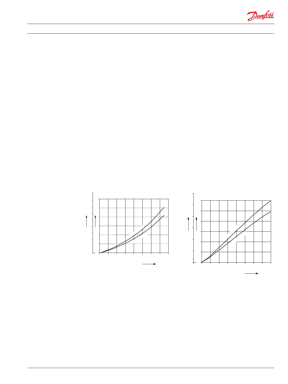
Charge pump flow and power curves, 14/17 cm³
Charge pressure: 20 bar [290 psi]
Viscosity: 11 mm²/s [63 SUS]
Temperature: 80°C [176°F]
Charge pump power requirements
00
1.0
9.0
8.0
7.0
6.0
5.0
4.0
2.0
3.0
1
2
3
4
5
6
HP
kW
17 cm
3
[1.04 in
3
/rev]
14 cm
3
[0.85 in
3
/rev]
P003 336E
0 500 1500
1000 2000
Speed min
-1
(rpm)
3000 4000
2500 3500
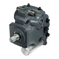
Charge pump flow
0
1
3
6
9
12
15
18
10
20
30
40
50
60
US gal/min
l/min
17 cm
3
[1.04 in
3
/rev]
14 cm
3
[0.85 in
3
/rev]
P003 334E
0 500 1500
1000 2000
Speed min
-1
(rpm)
3000 4000
2500 3500
Technical Information H1 Axial Piston Single Pumps, Size 069/078
Technical specifications
11062169 • Rev 0700 • November 2015 9