A
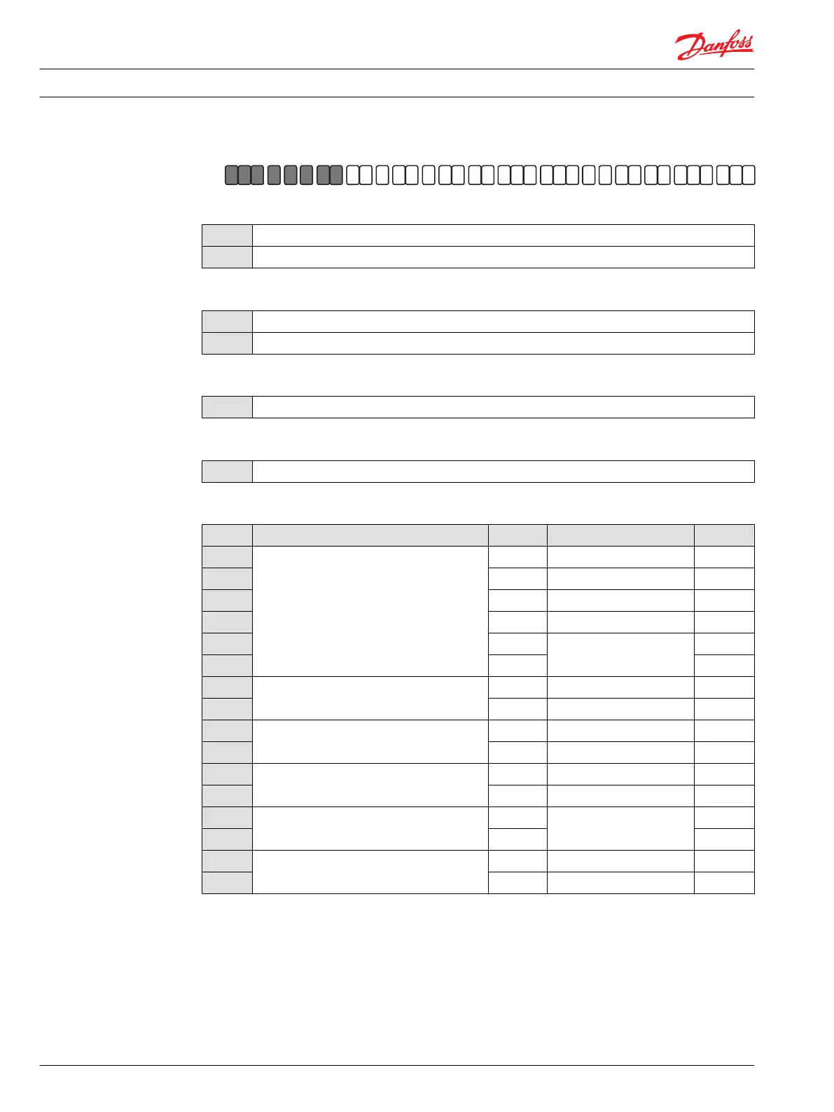
G H J K M N S T V W X YZ D EF
A
H1P
A B
Displacement
069
69.2 cm
3
[4.22 in
3
]
078
78.1 cm
3
[4.77 in
3
]
A – Rotation
L
Left hand (counter clockwise)
R
Right hand (clockwise)
B – Product version
A
Revision code
Z – Port configuration
A
Inch, Customer O-ring port sealing according to ISO 11926-1
D – Controls
Code Control type Voltage Manual OverRide; CCO Connector
A2
EDC — Electric Displacement Control
12 V — Deutsch
A3
24 V — Deutsch
A4
12 V MOR Deutsch
A5
24 V MOR Deutsch
E7
12 V
CCO with key C
Deutsch
E8
24 V Deutsch
A9
FNR — Forward-Neutral-Reverse
12 V MOR Deutsch
B1
24 V MOR Deutsch
A8
NFPE — Non Feedback Proportional Electric
1)
12 V MOR Deutsch
B8
24 V MOR Deutsch
A7
AC–1 — Automotive
2)
12 V MOR —
C2
24 V MOR —
B7
AC–2 — Automotive
2)
12 V
MOR and
Swash Plate Angle Sensor
—
C3
24 V —
F1
FDC — Fan Drive Control
3)
12 V — Deutsch
F2
24 V — Deutsch
1)
Align with options: E: Displacement limiters and W: Special hardware.
2)
Align with options: E: Displacement limiters, W: Special hardware, and Y: Special settings.
3)
Align with options: F: Orifices, E: Displacement limiters, M, N: Overpressure protection, and W: Special hardware.
Technical Information H1 Axial Piston Single Pumps, Size 069/078
Master model code H1P 069/078
10 11062169 • Rev 0700 • November 2015