A
G H J K M N S T V W X YZ D EF
A
H1P
A B
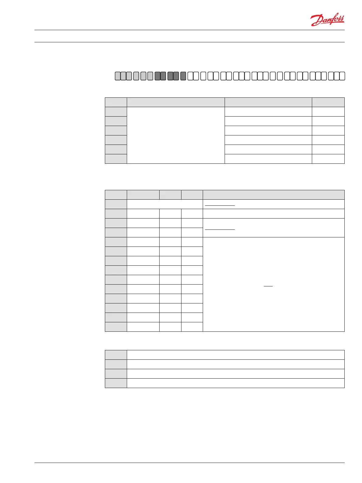
D – Controls (continued)
Code Control type CCO, NSS Connector
M1
MDC — Manual Displacement Control
1)
— —
M2
Neutral Start Switch Deutsch
M3
12V CCO Deutsch
M4
24V CCO Deutsch
M5
12V CCO and Neutral Start Switch Deutsch
M6
24V CCO and Neutral Start Switch Deutsch
1)
Align with options F: Orifices and Y: Settings for adjustment (if applicable).
F – Orifices (mm)
Code Tank (A+B) P A / B Note
C3
No orifice Not to be used for FDC controls and mobile applications.
C2
– – 1.3 –
C1
– – 0.8
Not to be used for FDC controls.
C4
– – 1.8
C6
1 – –
To be used for MDC controls only.
C7
1.3 – –
C8
0.6 0.8 –
C9
0.6 1 –
D1
0.8 1 –
D2
0.8 1.3 –
D3
1 1.3 –
D4
1 1.3 1.3
D5
0.6 0.6 0.8
D6
1.3 1.3 –
E – Displacement limiter
N
None
C
No limiters, with nested springs, required for NFPE / AC / FDC
1)
B
Adjustable externally
D
Adjustable externally with nested springs, required for NFPE / AC / FDC
1)
1)
Align with option: Y: Settings for adjustment (if applicable).
Technical Information H1 Axial Piston Single Pumps, Size 069/078
Master model code H1P 069/078
11062169 • Rev 0700 • November 2015 11