Bottom section
(c) always shows the state of the adjustable frequency
drive in status mode.
Press [Status] to toggle between three status readout
displays.
Operating variables with dierent formatting are shown in
each status screen. See the examples below.
Several values or measurements can be linked to each of
the displayed operating variables. The values/
measurements to be displayed can be dened via
parameter 0-20 Display Line 1.1 Small,
parameter 0-21 Display Line 1.2 Small,
parameter 0-22 Display Line 1.3 Small,
parameter 0-23 Display Line 2 Large and
parameter 0-24 Display Line 3 Large, which can be accessed
via [Quick Menu], Q3 Function Set-ups, Q3-1 General
Settings, Q3-13 Display Settings.
Each value/measurement readout parameter selected in
parameter 0-20 Display Line 1.1 Small to
parameter 0-24 Display Line 3 Large has its own scale and
number of digits after a possible decimal point. Larger
numeric values are displayed with few digits after the
decimal point.
Ex.: Current readout
5.25 A; 15.2 A 105 A.
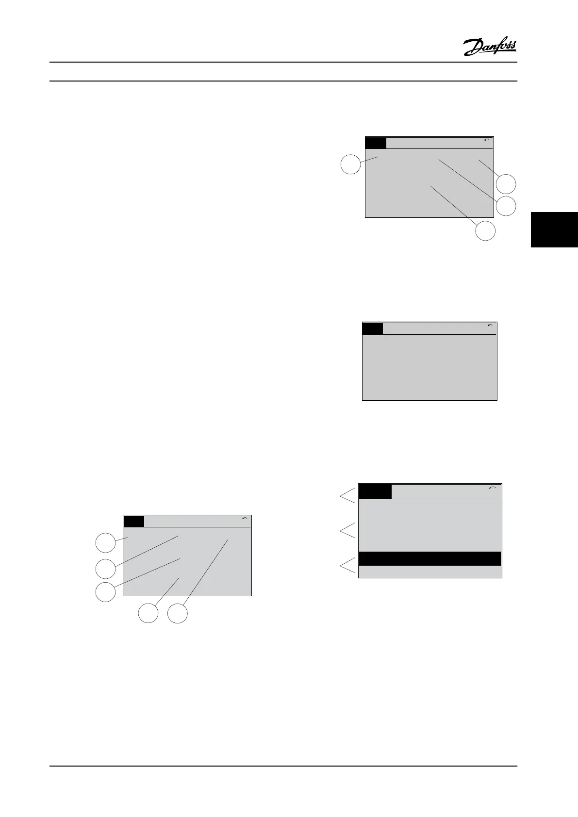
Status display I
This readout state is standard after start-up or initialization.
Press [INFO] to obtain information about the value/
measurement linked to the displayed operating variables
(1.1, 1.2, 1.3, 2, and 3).
See the operating variables shown in the display in
Figure 5.2. 1.1, 1.2 and 1.3 are shown in small size. 2 and 3
are shown in medium size.
1.1
2
3
1.3
1.2
130BP041.10
799 RPM
Auto Remote Ramping
1 (1)
36.4 kW7.83 A
0.000
53.2%
Status
Figure 5.2 Example of Status Display I
Status display II
See the operating variables (1.1, 1.2, 1.3, and 2) shown in
the display in Figure 5.3.
In the example, speed, motor current, motor power and
frequency are selected as variables in the rst and second
lines.
1.1, 1.2 and 1.3 are shown in small size. 2 is shown in large
size.
1.1
1.2
2
1.3
130BP062.10
207RPM
Auto Remote Running
1 (1)
24.4 kW5.25A
6.9Hz
Status
Figure 5.3 Example of Status Display II
Status display III
This state displays the event and action of the smart logic
control.
130BP063.10
778 RPM
Auto Remote Running
1 (1)
4.0 kW0.86 A
State: 0 o 0 (o)
When: -
Do: -
Status
Figure 5.4 Example of Status Display III
Display contrast adjustment
Press [status] and [
▲
] for darker display.
Press [status] and [
▼
] for brighter display.
Top section
Middle section
Bottom section
Status
43 RPM
1.4 Hz
Auto Remote Running
! Pwr.card temp (W29)
2.9%
5.44 A 25.3 kW
1(1)
130BP074.10
!
Figure 5.5 Display Sections
LEDs
If certain threshold values are exceeded, the alarm and/or
warning LED lights up. A status and alarm text appear in
the display.
The On LED is activated when the adjustable frequency
drive receives power from AC line voltage, a DC bus
terminal, or a 24 V external supply. At the same time, the
backlight is on.
•
Green LED/On: Control section is working.
•
Yellow LED/Warn.: Indicates a warning.
How to Operate the Adjustab...
Instruction Manual
MG11F522 Danfoss A/S © 08/2014 All rights reserved. 67
5 5
 Loading...


