•
•
•
•
•
•
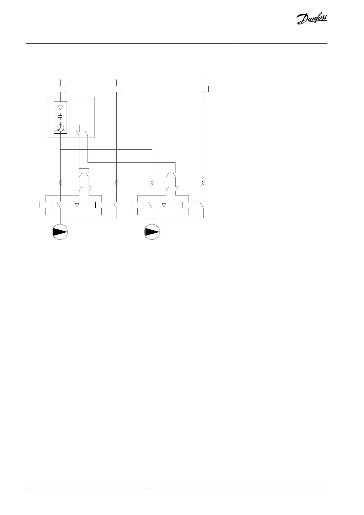
8.1.14 Wiring Configuration for Lead Pump Alternation
Illustration 71: Lead Pump Alternation Wiring Diagram
Every pump must be connected to 2 contactors (K1/K2 and K3/K4) with a mechanical interlock. Apply thermal relays or other motor
overload protection devices according to local regulation and/or individual demands.
Relay 1 (R1) and relay 2 (R2) are the built-in relays in the drive.
When all relays are de-energized, the 1
st
built-in relay that is energized cuts in the contactor corresponding to the pump con-
trolled by the relay. For example, relay 1 cuts in contactor K1, which becomes the lead pump.
K1 blocks for K2 via the mechanical interlock, preventing mains from being connected to the output of the drive (via K1).
Auxiliary break contact on K1 prevents K3 from cutting in.
Relay 2 controls contactor K4 for on/off control of the fixed-speed pump.
At alternation, both relays de-energize and now relay 2 is energized as the 1
st
relay.
For a detailed description of commissioning for mixed pump and master/slave applications, refer to VLT® Extended/Advanced Cas-
cade Controllers MCO 101/MCO 102 Operating Guide.
AQ262141314214en-000301 / 130R0880130 | Danfoss A/S © 2021.11
Wiring Configuration Examples
VLT® HVAC Drive FC 102
Operating Guide
 Loading...


