Automatic capacitor control [p.u.]
(1)(2)
Capacitor always connected [p.u.]
(1)
Capacitor always open [p.u.]
(1)
1
Positive numbers indicate lagging reactive currents. Negative numbers indicate leading currents.
2
The capacitor connecting contactor switches at 20% load.
10.7.2 Line Reactor Specifications
All line reactors are equipped with thermal switches and are looped to the enclosed drive for overtemperature protection. For more
details, refer to the Control Compartment section. The line reactor configuration varies depending on the enclosure and voltage re-
quired.
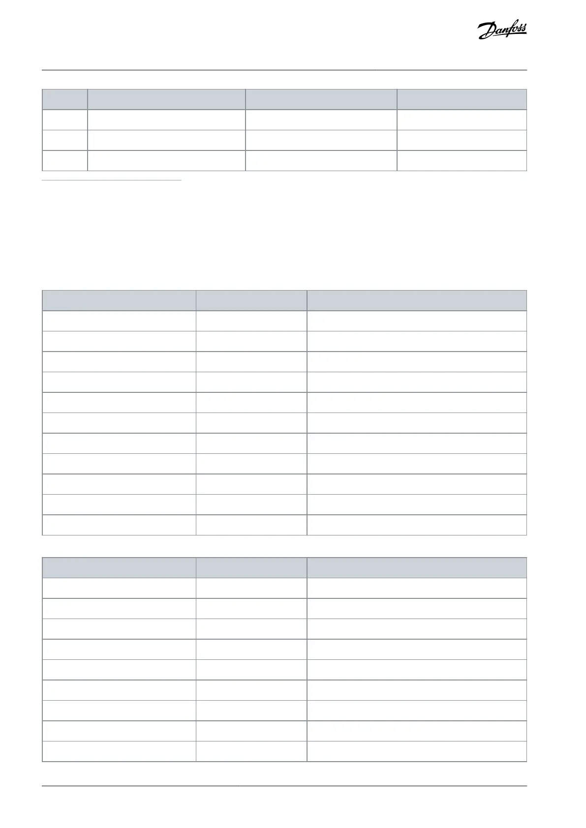
Table 103: Line Reactor Configuration for D9h–D10h and E5h–E6h Enclosures, 380–480 V
Table 104: Line Reactor Configuration for D9h–D10h and E5h–E6h Enclosures, 525–690 V
AQ262141314214en-000301 / 130R0880166 | Danfoss A/S © 2021.11
Specifications
VLT® HVAC Drive FC 102
Operating Guide
 Loading...


