5 RS485-based Option Boards
5.1 Common Information for the OPTE3/E5 and OPTE2/E8 Option Boards
5.1.1 The OPTE3/E5 and OPTE2/E8 Option Board Layout
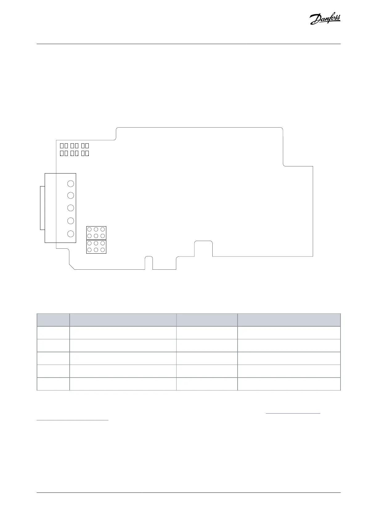
The fieldbus is connected to the OPTE3 and OPTE2 option boards using a 5-pin pluggable bus connector. The fieldbus is connected
to the OPTE5 and OPTE8 option boards using a Sub- D9 connector. The option boards have the same layout regarding connectors,
LEDs and jumpers. The following figure shows the board layout. OPTE5 and OPTE8 use a different fieldbus connector.
Illustration 12: The OPTE3/E5 and OPTE2/E8 Option Board Layout
Because of the different connectors, the signal pin layout in the cable connections are different. The following table describes the
signals.
Table 8: The Connections of the Option Board
Connector pin Screw plug OPTE3, OPTE2
Supply voltage - plus (5V)
Receive/Transmit data - plus (B)
Receive/ Transmit data - minus (A)
Data Ground (reference potential for VP)
5.1.2 The Jumpers in the OPTE3/E5 and OPTE2/E8 Option Boards
The jumper settings for these option boards are described in this chapter. For jumper locations, see 5.1.1 The OPTE3/E5 and
OPTE2/E8 Option Board Layout.
If the AC drive is the last device on the bus, bus termination has to be set.
AN338644703080en-0002 / DPD02156 | 39Danfoss A/S © 2022.08
RS485-based Option Boards
VACON® RS485 and CAN Bus Option Boards
Installation Guide