Cable shield is connected directly to PE (factory de-
fault setting).
Cable shield is connected to PE through RC.
Cable shield is connected to PE through RC.
Illustration 36: The Settings of the Jumper X1, Cable Shield Grounding, Positions A, B, and C.
Bus termination is OFF (factory default setting).
Illustration 37: The Settings of the Jumper X6, Bus Terminal Resistor, positions A and B
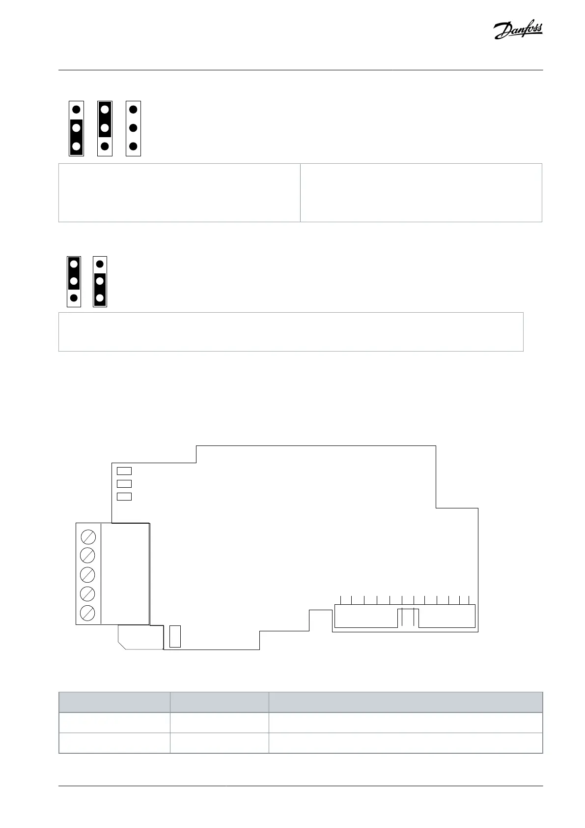
6.3 The OPTC7 Option Board
6.3.1 The OPTC7 Option Board Layout
The OPTC7 option board is a DeviceNet fieldbus board that uses CAN bus as the communication layer.
Illustration 38: The OPTC7 Option Board Layout
Table 15: The Connections of the Option Board
CAN GND V- isolated digital ground reference
AN338644703080en-0002 / DPD02156 | 51Danfoss A/S © 2022.08
CAN Type and Other Fieldbus
Option Boards
VACON® RS485 and CAN Bus Option Boards
Installation Guide