CAN bus connector pin 3 (shield) is connected to the
drive chassis with a high-impedance RC circuit. This
option is recommended when equipotential bond-
ing is poor.
CAN bus connector pin 3 (shield) is connected di-
rectly to the drive chassis (factory default setting).
This option is recommended when equipotential
bonding is good.
CAN bus connector pin 3 is not connected.
Illustration 34: The Settings of the Jumper X6, CAN Bus Cable Shield Grounding, positions A, B, and C
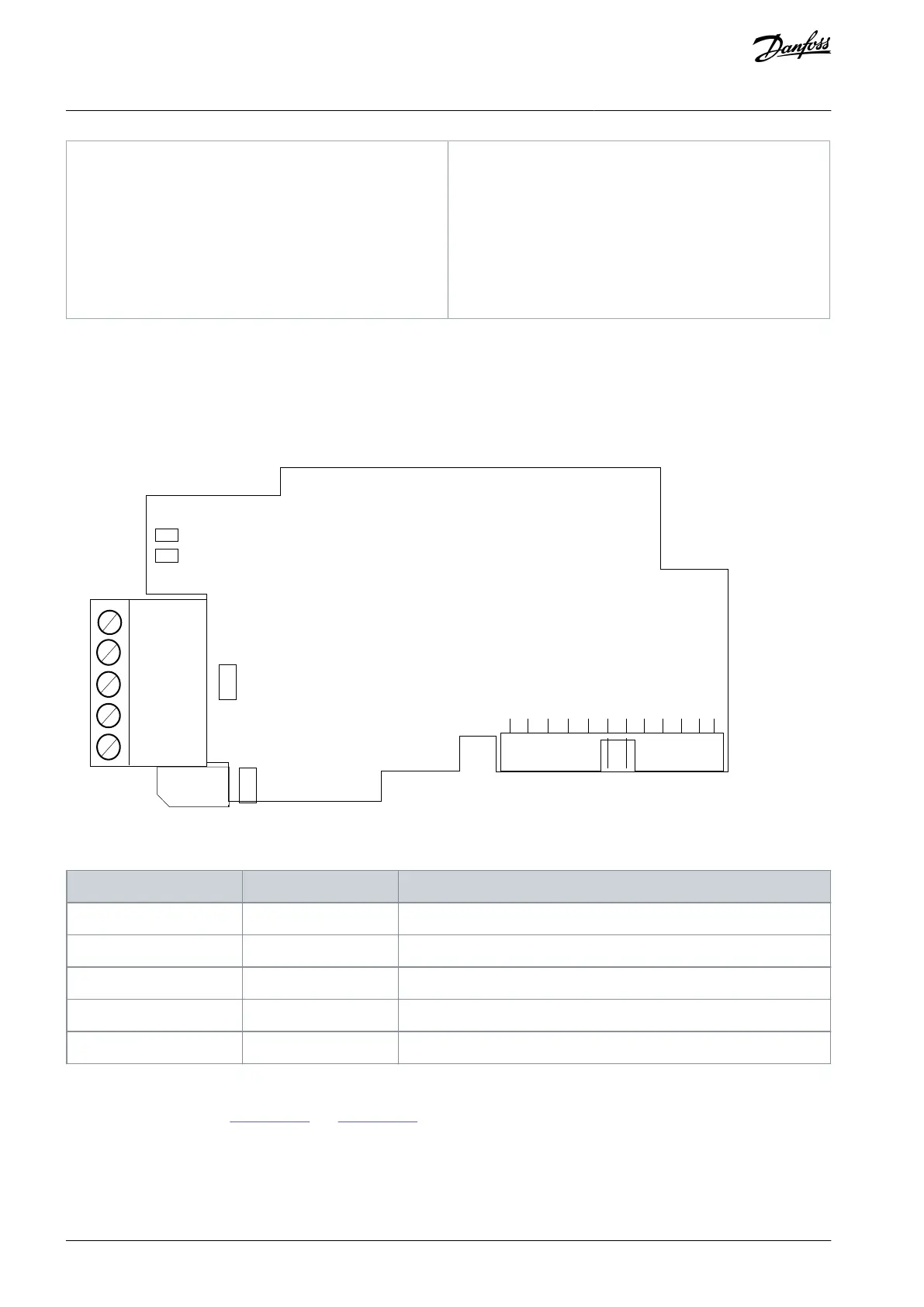
6.2 The OPTC6 Option Board
6.2.1 The OPTC6 Option Board Layout
Fieldbus is connected to the OPTC6 option board using a 5-pin screw plug.
Illustration 35: The OPTC6 Option Board Layout
Table 14: The Connections of the Option Board
CAN GND V- isolated digital ground reference
Not connected for CANopen.
6.2.2 The Jumpers in the OPTC6 Option Board
For the jumper settings, see Illustration 36 and Illustration 37.
AN338644703080en-0002 / DPD0215650 | Danfoss A/S © 2022.08
CAN Type and Other Fieldbus
Option Boards
VACON® RS485 and CAN Bus Option Boards
Installation Guide