1
A
B
2 3
1 2 3
1 2 3
e30bi076.10
1 2 3
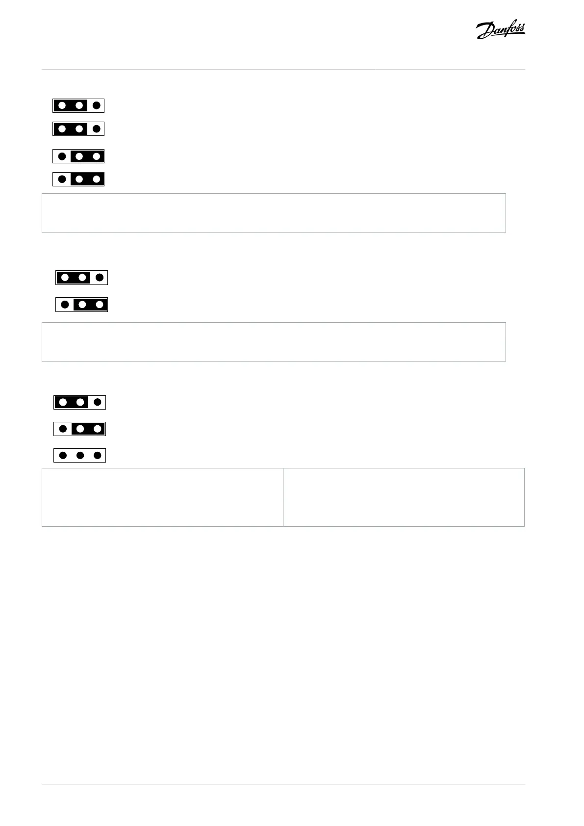
Bus termination is OFF (factory default setting).
Illustration 13: The Settings of the Jumper X13, Termination Resistor, Positions A and B
GND is connected to cable shield.
GND is not connected to cable shield (factory default setting).
Illustration 14: The Settings of the Jumper X14, Grounding, Upper Row, Positions A and B
1
A
B
C
2 3
1 2 3
1 2 3
e30bi078.10
Cable shield is connected directly to PE (factory de-
fault setting).
Cable shield is connected to PE through RC.
Cable shield is not connected.
Illustration 15: The Settings of the Jumper X14, Grounding, Lower Row, Positions A, B, and C
5.2 The OPTC3/C5 Option Board
Fieldbus is connected to the OPTC3 option board using a 5-pin pluggable bus connector, and to the OPTC5 option board using a
Sub-D9 connector. OPTC5 uses a different fieldbus connector.
AN338644703080en-0002 / DPD0215640 | Danfoss A/S © 2022.08
RS485-based Option Boards
VACON® RS485 and CAN Bus Option Boards
Installation Guide