The termination is activated
The termination is deactivated
The termination is activated with a jumper
Illustration 24: Setting the Termination Resistance
5.5 The OPTC2/C8 and OPTCJ Option Boards
Fieldbus is connected to the OPTC2 and OPTCJ option boards using a 5-pin pluggable bus connector, and to the OPTC8 option
board using a Sub-D9 connector. OPTC2 and OPTCJ have a common physical board layout. OPTC8 uses a different fieldbus connec-
tor.
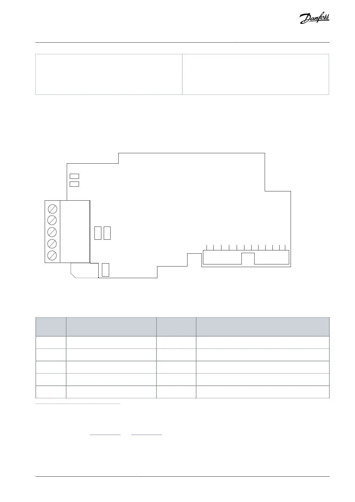
Illustration 25: The OPTC2, OPTC8, and OPTCJ option board layout
Due to the different connectors, the signal pin layouts in cable connections are different. The following table describes the signals.
Table 11: The Connections of the Option Board
Connector pin Screw plug OPTC2,
OPTCJ
No connection in OPTC2 or OPTCJ. In OPTC8 cable shield.
Supply voltage - plus (5 V)
Receive/Transmit data - plus (B)
Receive/ Transmit data - minus (A)
Data Ground (reference potential for VP)
1
Use pin 1 to bypass the cable shield to the next slave in OPTC2 and OPTCJ with screw plug.
5.5.1 Jumpers in the OPTC2/C8, and OPTCJ Option Boards
For jumper settings, see
Illustration 26 and Illustration 27. The jumper X1 has no effect on OPTC2 or OPTCJ.
AN338644703080en-0002 / DPD02156 | 45Danfoss A/S © 2022.08
RS485-based Option Boards
VACON® RS485 and CAN Bus Option Boards
Installation Guide