Cable shield is connected directly to PE.
Cable shield is connected to PE through RC (factory default setting).
Illustration 26: The settings of the jumper X1 for OPTC8, Cable Shield Grounding, positions A, and B
Bus termination is OFF (factory default setting).
Illustration 27: The Settings of the Jumper X4, Bus Terminal Resistor, Positions A, and B
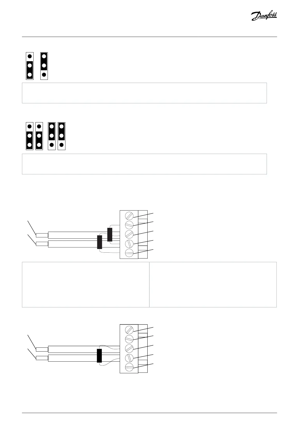
If setting the jumpers does not give the desired outcome, add biasing resistors, termination resistors or both. For biasing with
OPTC2, connect the resistors between pins 2 and 4 and between pins 3 and 5. For termination with OPTC2, connect the resistor
between pins 3 and 4.
Illustration 28: The Fail-safe Biasing in OPTC2
AN338644703080en-0002 / DPD0215646 | Danfoss A/S © 2022.08
RS485-based Option Boards
VACON® RS485 and CAN Bus Option Boards
Installation Guide