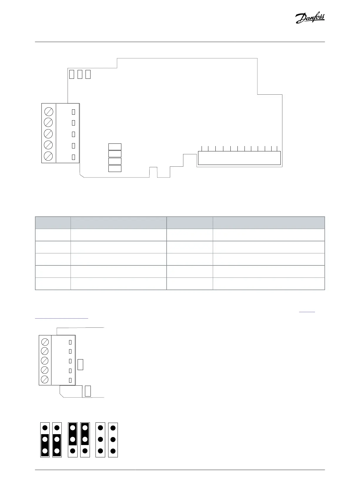
Illustration 16: The OPTC3/C5 option board layout
Due to the different connectors, the signal pin layouts in cable connections are different. The following table describes the signals.
Table 9: The Connections of the Option Board
Connector pin Screw plug OPTC3
Supply voltage - plus (5 V)
Receive/Transmit data - plus (B)
Receive/ Transmit data - minus (A)
Data Ground (reference potential for VP)
5.2.1 Jumpers in the OPTC3/C5 Option Board
The jumper settings for these option boards are described in this chapter. For jumper locations on the option board, see 5.2 The
OPTC3/C5 Option Board.
Illustration 17: Jumper Locations on OPTC3/C5
AN338644703080en-0002 / DPD02156 | 41Danfoss A/S © 2022.08
RS485-based Option Boards
VACON® RS485 and CAN Bus Option Boards
Installation Guide