Bus termination is OFF (factory default setting)
Bus termination is OFF. Termination resistor is not
connected.
Illustration 18: The Settings of the Jumper X6 on Board, Termination Resistor, Positions A, B, and C
Cable shield is connected directly to PE.
Cable shield is connected to PE through RC (factory
default setting).
Cable shield is connected to PE through RC when
jumper is not connected.
Illustration 19: The Settings of the Jumper X1 on Board, Cable Shield Grounding, Positions A, B, and C
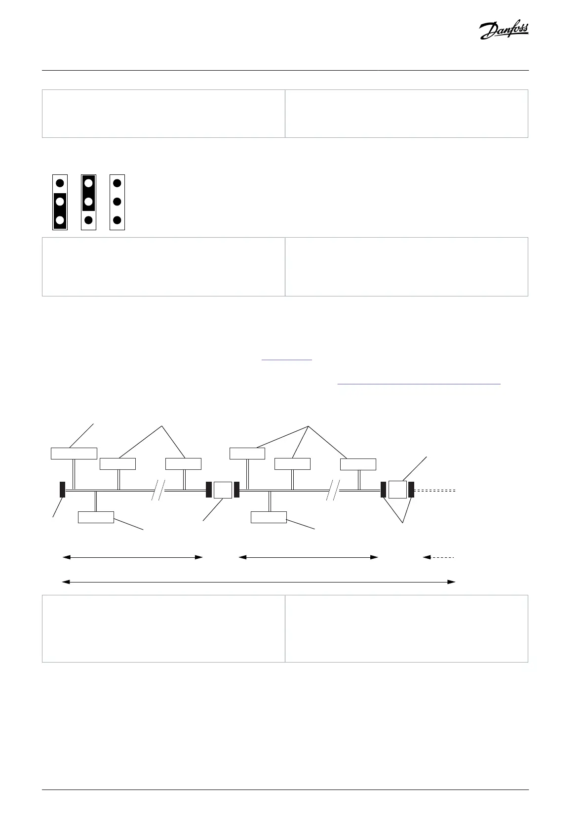
5.3 Cabling and bus termination for PROFIBUS option boards
The PROFIBUS devices are connected in a bus line. Up to 32 stations (master or slaves) can be connected in one segment. The bus is
terminated at the beginning and end of each segment (see Illustration 20). The bus termination at both ends of the segment must
always be powered. When more than 32 stations are used, repeaters (line amplifiers) must be used to connect the bus segments.
The maximum cable length depends on the transmission speed and cable type (4.1 General Cabling Instructions for Fieldbus). The
specified cable length can be increase by using repeaters. The use of more than three repeaters in series is not recommended.
R
R
e30bi095.10
1
2
2
3
4
2
3
2
5 5
6
4
Maximum of 126 stations (4-segment)
Illustration 20: The Cabling and Bus Termination for PROFIBUS DP Option Boards
5.4 The OPTE2/OPTE8 Option Boards
5.4.1 Exceptions in Connector Pin Outs
When replacing the OPTC2 option board with the OPTE2/E8 option board, note that the pins for Receive/Transmit data - Plus (B)
and Receive/Transmit data - Minus (A) have switched places. In OPTC2/C8, the first pin is not connected to the cable shield.
AN338644703080en-0002 / DPD0215642 | Danfoss A/S © 2022.08
RS485-based Option Boards
VACON® RS485 and CAN Bus Option Boards
Installation Guide