Hardware versions 70CVB01605 (141X4171) and 70CVB01817 (141X4403)
Hardware versions 70CVB01124 (141X3915) and 70CVB01555 (141X4133)
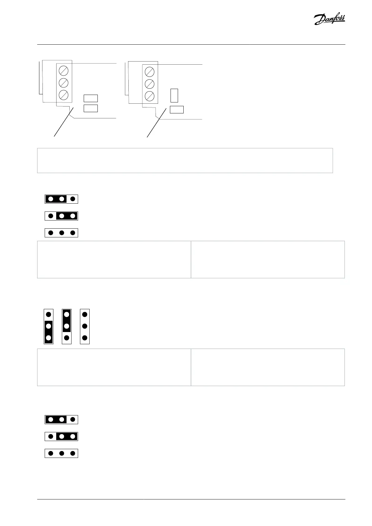
Illustration 31: The Location of the Jumpers
1
A
B
C
2 3
1 2 3
1 2 3
e30bi078.10
Termination resistor 120 Ω is connected.
Termination resistor is not connected to the CAN
bus (factory default setting).
Termination resistor is not connected to the CAN
bus.
Illustration 32: The Settings of the Jumper X7 on 70CVB01605 (141X4171) and 70CVB01817 (141X4403), Bus Terminal Resistor, Positions A, B,
and C
Termination resistor 120 Ω is connected.
Termination resistor is not connected to the CAN
bus (factory default setting).
Termination resistor is not connected to the CAN
bus.
Illustration 33: The Settings of the Jumper X7 on 70CVB01124 (141X3915) and 70CVB01555 (141X4133), Bus Terminal Resistor, Positions A, B,
and C
1
A
B
C
2 3
1 2 3
1 2 3
e30bi078.10
AN338644703080en-0002 / DPD02156 | 49Danfoss A/S © 2022.08
CAN Type and Other Fieldbus
Option Boards
VACON® RS485 and CAN Bus Option Boards
Installation Guide