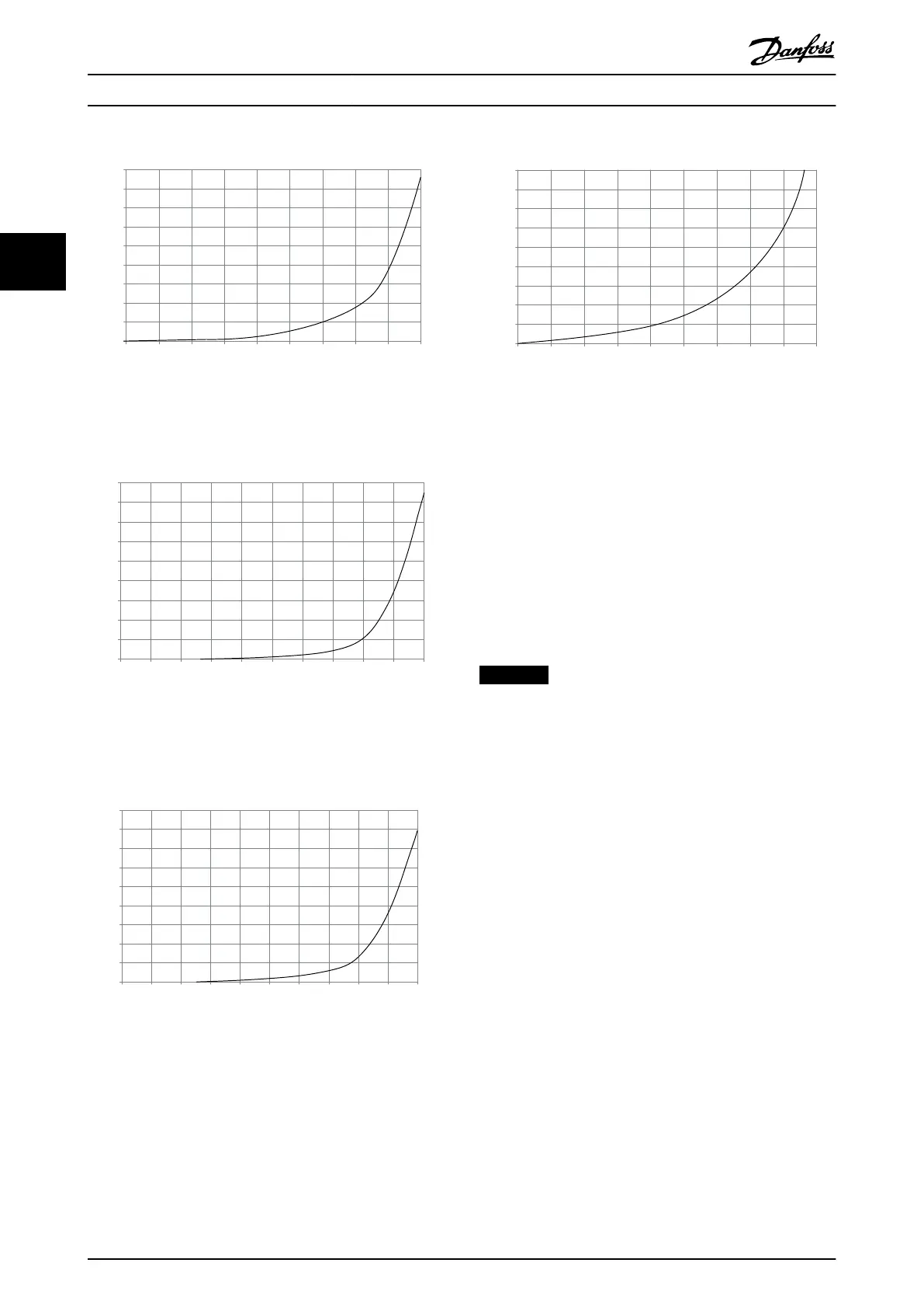
90
80
70
60
50
40
30
20
10
0
0 0.5 4.9 13 27.3 45.9 66 89.3 115.7 147
(%)
(Pa)
Pressure Increase
Drive Derating
130BB007.10
Illustration 3.1 D frame derating vs. pressure change
frequency converter air flow: 450 cfm (765 m
3
/h)
90
80
70
60
50
40
30
20
10
0
(%)
Drive Derating
0 0 0.1 3.6 9.8 21.5 43.4 76 237.5 278.9
(Pa)
Pressure Change
130BB010.10
147.1
Illustration 3.2 E frame derating vs. pressure change (small
fan), P355T7-P400T7
frequency converter air flow: 650 cfm (1105 m
3
/h)
90
80
70
60
50
40
30
20
10
0
(%)
Drive Derating
0 0.2 0.6 2.2 5.8 11.4 18.1 30.8 152.8 210.8
(Pa)
Pressure Change
130BB011.10
69.5
Illustration 3.3 E frame derating vs. pressure change (large
fan), P500T7-P560T7
frequency converter air flow: 850 cfm (1445m
3
/h)
90
80
70
60
50
40
30
20
10
0
(%)
Drive Derating
0 25 50 75 100 125 150 175 225
130BB190.10
200
Pressure Change
Illustration 3.4 F1, F2, F3, F4 frame derating vs. pressure
change
frequency converter air flow: 580 cfm (985 m
3
/h)
3.1.9
Selection of Transformer
•
The output of the HT-transformer must be
specified for 630 V.
•
It is recommended to use 2 separate transformers
for 630 V and the 400 V and these transformers
should be physically separated. The 400 V
transformer must be close to or in the E-house to
have a short ground cable.
NOTICE
Danfoss reviews/evaluates the LCL filter design for each
application especially when the new transformer is used.
Crane System Design Operating Instructions
10 Danfoss A/S © Rev. 05/2014 All rights reserved. MG33X402
33