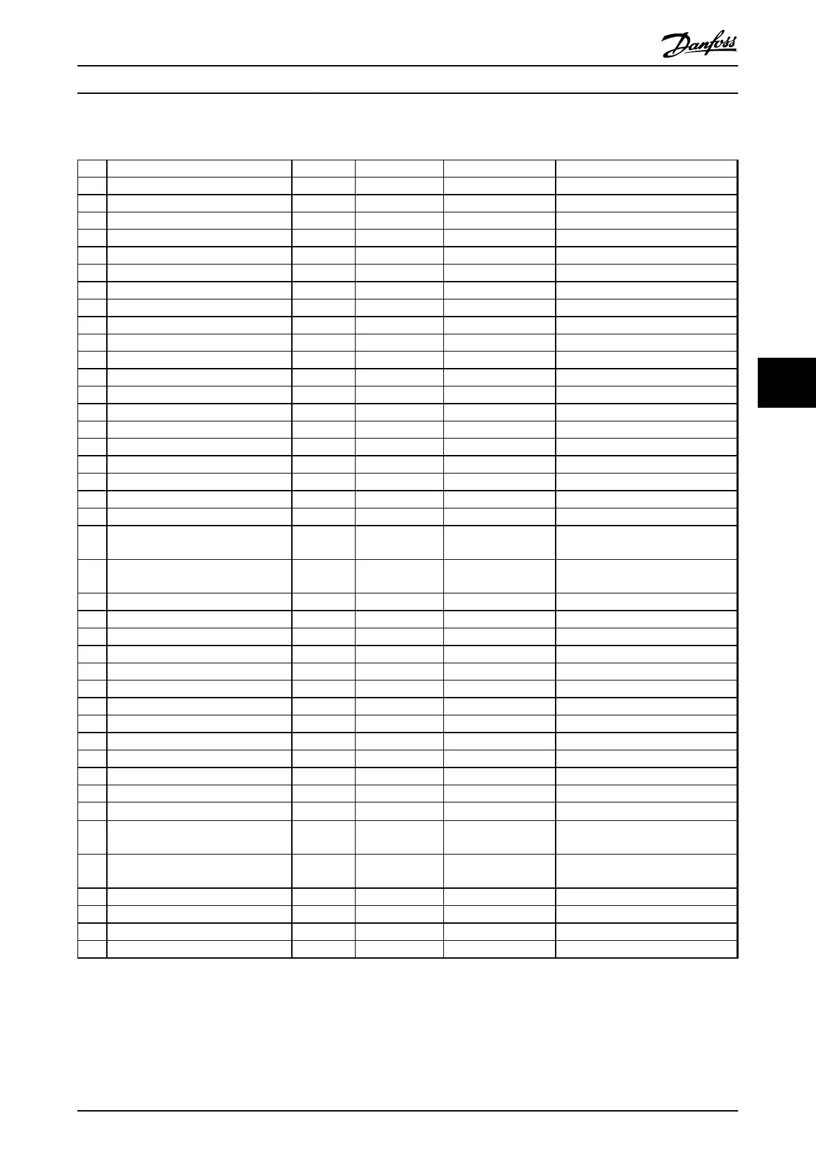
6.12 Warnings/Alarm Messages
No. Description Warning Alarm/Trip Alarm/Trip Lock Parameter Reference
1 10 Volts low X
5 DC link voltage high X
6 DC link voltage low X
7 DC over-voltage X X
8 DC under voltage X X
9 Inverter overloaded X X
13 Over Current X X X
14 Earth Fault X X X
15 Hardware mismatch X X
16 Short Circuit X X
17 Control word time-out (X) (X)
8-04 Control Word Timeout Function
23 Internal Fan Fault X
14-53 Fan Monitor
24 External Fan Fault X
14-53 Fan Monitor
29 Heatsink temp X X X
33 Inrush Fault X X
34 Fieldbus communication fault X X
36 Mains failure X X
37 Phase imbalance X
38 Internal Fault X X
39 Heatsink sensor X X
40 Overload of Digital Output Terminal
27
(X)
5-00 Digital I/O Mode, 5-01 Terminal
27 Mode
41 Overload of Digital Output Terminal
29
(X)
5-00 Digital I/O Mode, 5-02 Terminal
29 Mode
46 Pwr. card supply X X
47 24 V supply low X X X
48 1.8 V supply low X X
59 Current limit X
62 Output Frequency Limit X
64 Voltage Limit X X
65 Control Board Over-temperature (X) (X) X
66 Heat sink Temperature Low X
67 Option Configuration has Changed X
68 Safe Stop Alarm/trip only
69 Pwr. Card Temp X X
70 Illegal FC configuration X
71 Output voltage limit X
X
1)
77 Reduced power mode X
Parameter 14-59 Actual Number of
Inverter Units
78 Power Unit Setup X
Parameter 14-59 Actual Number of
Inverter Units
79 Illegal PS config X X
80 AFEInitialized to Default Value X
250 New spare part X
14-23 Typecode Setting
251 New Type Code X X
Table 6.6 Alarm/Warning Code List
(X) Dependent on parameter
How to Programme
Operating Instructions
MG33X402 Danfoss A/S © Rev. 05/2014 All rights reserved. 65
6 6