4.4 Electrical Installation
Switch Mode
Power Supply
Analog Output
Interface
relay1
* relay2
ON=Terminated
OFF=Open
50 (+10 V OUT)
53 (A IN)
54 (A IN)
55 (COM A IN)
0/4-20 mA
12 (+24V OUT)
13 (+24V OUT)
37 (D IN)
18 (D IN)
20 (COM D IN)
10Vdc
15mA 130/200mA
+ - + -
(COM A OUT) 39
(A OUT) 42
(P RS-485) 68
(N RS-485) 69
(COM RS-485) 61
0V
5V
S801
0/4-20 mA
RS-485
RS-485
03
+10Vdc
0/-10Vdc -
+10Vdc
+10Vdc
0/4-20 mA
0/-10Vdc -
240Vac, 2A
24Vdc
02
01
05
04
06
240Vac, 2A
24V (NPN)
0V (PNP)
0V (PNP)
24V (NPN)
19 (D IN)
24V (NPN)
0V (PNP)
27
24V
0V
(D IN/OUT)
0V (PNP)
24V (NPN)
(D IN/OUT)
0V
24V
29
24V (NPN)
0V (PNP)
0V (PNP)
24V (NPN)
33 (D IN)
32 (D IN)
1 2
ON
S201
ON
21
S202
ON=0/4-20mA
OFF=0/-10Vdc -
+10Vdc
400Vac, 2A
P 5-00
21
ON
S801
*
*
3 Phase
power
input
91 (L1)
92 (L2)
93 (L3)
PE
95
DC+
DC-
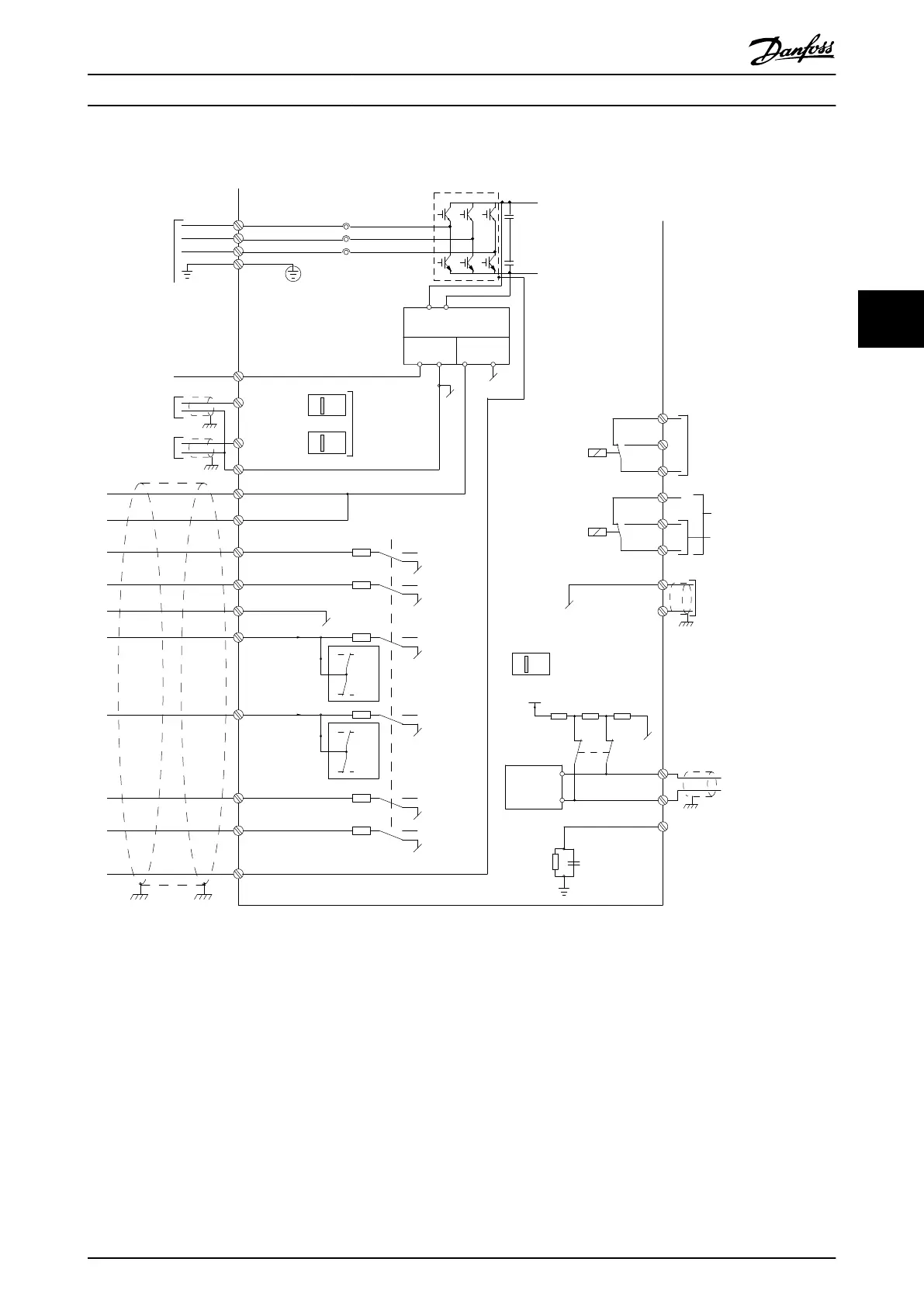
Illustration 4.12 Diagram showing all electrical terminals without options.
A = analog, D = digital
Terminal 37 is used for Safe Stop. For instructions on Safe Stop installation please refer to the VLT
®
Frequency Converters - Safe
Torque Off Operating Instructions.
How to Install Operating Instructions
MG33X402 Danfoss A/S © Rev. 05/2014 All rights reserved. 35
4 4