3.2 Assembling the Frequency Converter
System
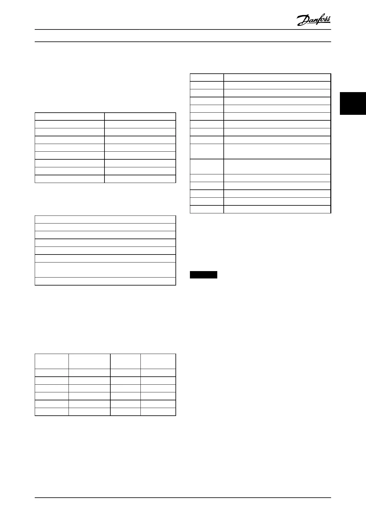
3.2.1 Tools Required
Operating Instructions for the FC Series.
Metric socket set 7–19 mm
Socket extensions 1/4" drive size, 4", 6" and 12"
Torx driver set T8-T50
Torque wrench 0.675–19 Nm (6–168 in-lbs)
Needle nose pliers
Magnetic sockets
Ratchet
Hex wrench set
Screwdrivers Standard and Phillips
Table 3.3 Tools Required
Additional Tools Recommended for Testing
Digital volt/ohmmeter (rated for 1200 V DC)
Voltmeter
Oscilloscope
Clamp-on style ammeter
Test cable PN 176F8766
Signal test board PN 176F8437
Power supply: 500-1000 V DC, 250 mA to supply external power
to 4 power cards and the control card.
Power supply : 24 V DC, 2 A for external 24 V power supply.
Table 3.4 Additional Tools
3.2.2
General Tightening Torque Values
Table 3.5 tabulates the tightening torque values. The
tightening toque values for the rectifier and IGBT modules
are referred to in the instruction within the spare kits.
Shaft size Driver size
Torx/hex
Torque [in-
lbs]
Torque [Nm]
M4 T-20/7 mm 10 1.0
M5 T-25/8 mm 20 2.3
M6 T-30/10 mm 35 4.0
M8 T-40/13 mm 85 10
M10 T-50/17 mm 170 19
M12 18 mm/19 mm 170 19
Table 3.5 Torque Values
3.2.3
Exploded Views
Number Terminal and component description
1 Fan Voltage Supply (FVS)
2 Soft Charge Board (SC)
3 FVS Fuse (TB10)
4 SC Fuse (TB11)
5 Aux Fan Fuse
6 Fan Fuse
7 SMPS Fuse
8 Mains Terminals (R, S, T)
9 Aux Relay (TB12)
01 02 03 04 05 06
10 VSYNC (TB13) (Only for AFE Cabinet)
01-R, 02-S, 03-T
11 Control Card
12 MDCIC
13 Control Panel (Check the enlarged view)
14 DC Terminals (DC+ and DC-)
15 DC Bus Fuses
Table 3.6 Legend for Illustration 3.6 to Illustration 3.18
The rated voltage and maximum current magnitudes for
the AUX relay and VSYNC terminals are as follows:
AUX Relay: 240 V AC 2 A
VSYNC: 630 V 1 A
NOTICE
The control circuit including the control card terminal is
PELV isolated and it is also isolated from the power
circuit galvanically.
Crane System Design Operating Instructions
MG33X402 Danfoss A/S © Rev. 05/2014 All rights reserved. 11
3 3