The typical 1.2 MW LCL filter components are described
below:
1. Lc choke 100 uH
2. Lm choke 29 uH
3. Capacitor 10x 40 uF in delta, 30 pieces
4.
Resistors 90 mΩ 4000 W, 3 pieces
4.2 Pre-installation
4.2.1 Planning the Installation Site
Before performing the installation it is important to plan
the installation of the frequency converter. Neglecting this
may result in extra work during and after the installation.
Select the best possible operation site by considering the
followings:
•
Ambient operating temperature
•
Installation method
•
Cooling method
•
Position of the frequency converter
•
Cable routing
•
Power source supply configuration
•
Motor current rating with respect to the
frequency converter maximum current magnitude
•
Fuse arrangement, either built-in fuses or the
properly rated external fusees
4.2.2
Receiving the Frequency Converter
When receiving the frequency converters, please inspect
the frequency converters for any damage which may occur
during the transportation. When the damage is noticed,
please contact the shipping company immediately to claim
the damage and let Danfoss know the situation to work
for the corrective action.
4.2.3
Transportation and Unpacking
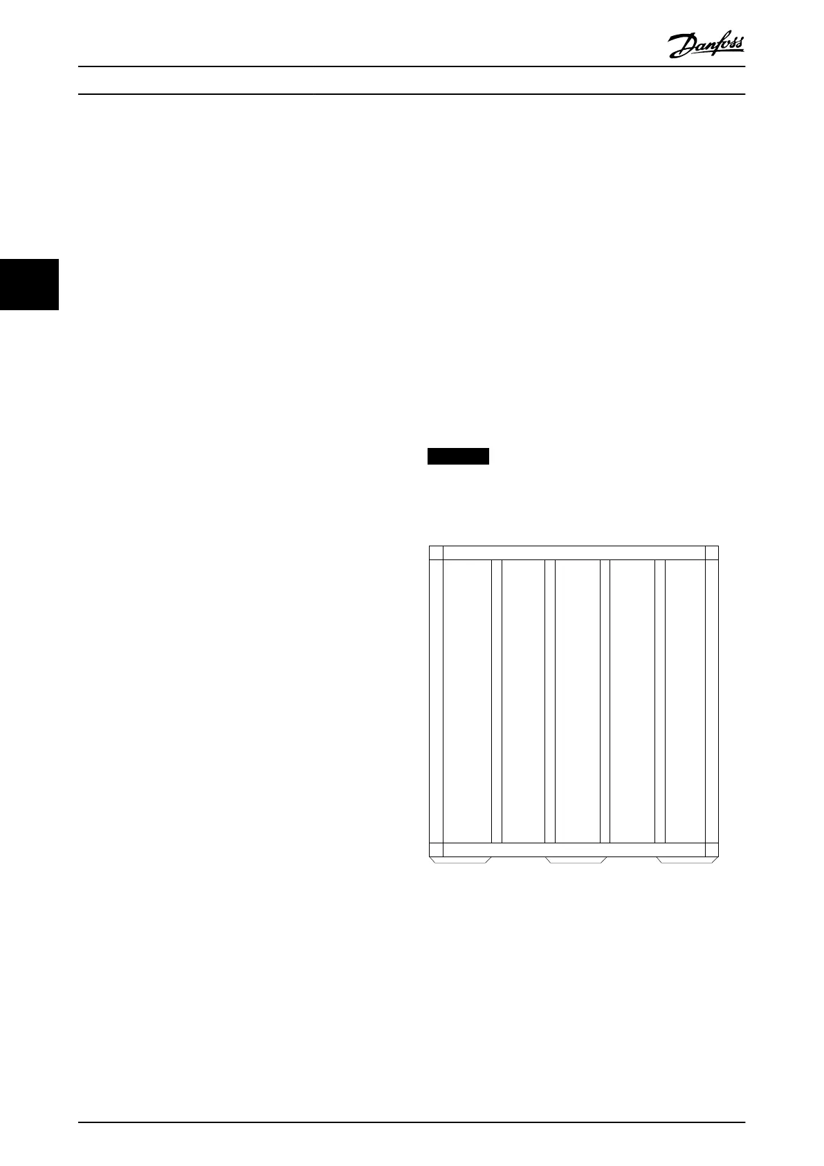
Illustration 4.2 and Illustration 4.3 show the front and side
views of the frequency converter, shipping crate, respec-
tively.
The unpacking procedure is as follows:
1. Remove clips from one long side panel (A) and all
around the top.
2. Remove the long side panel (A).
3. Remove the top panel (B).
4. Remove clips from one short side panel (C).
5. Remove the short side panel (C)
6. Remove the rest of the clips.
7. Remove the final two panels.
NOTICE
The package includes the plinth at the bottom of the
frequency converter. The plinth allows proper cooling of
the frequency converter during the shipment.
Illustration 4.2 Package Front View
How to Install Operating Instructions
24 Danfoss A/S © Rev. 05/2014 All rights reserved. MG33X402
44