16-65 Analog Output 42 [mA]
Range: Function:
0* [0 - 30 ] View the actual value at output 42 in mA. The
value shown reflects the selection in 6-50 Terminal
42 Output.
16-66 Digital Output [bin]
Range: Function:
0* [0 - 15 ] View the binary value of all digital outputs.
16-71 Relay Output [bin]
Range: Function:
0* [0 - 511 ] View the settings of all relays.
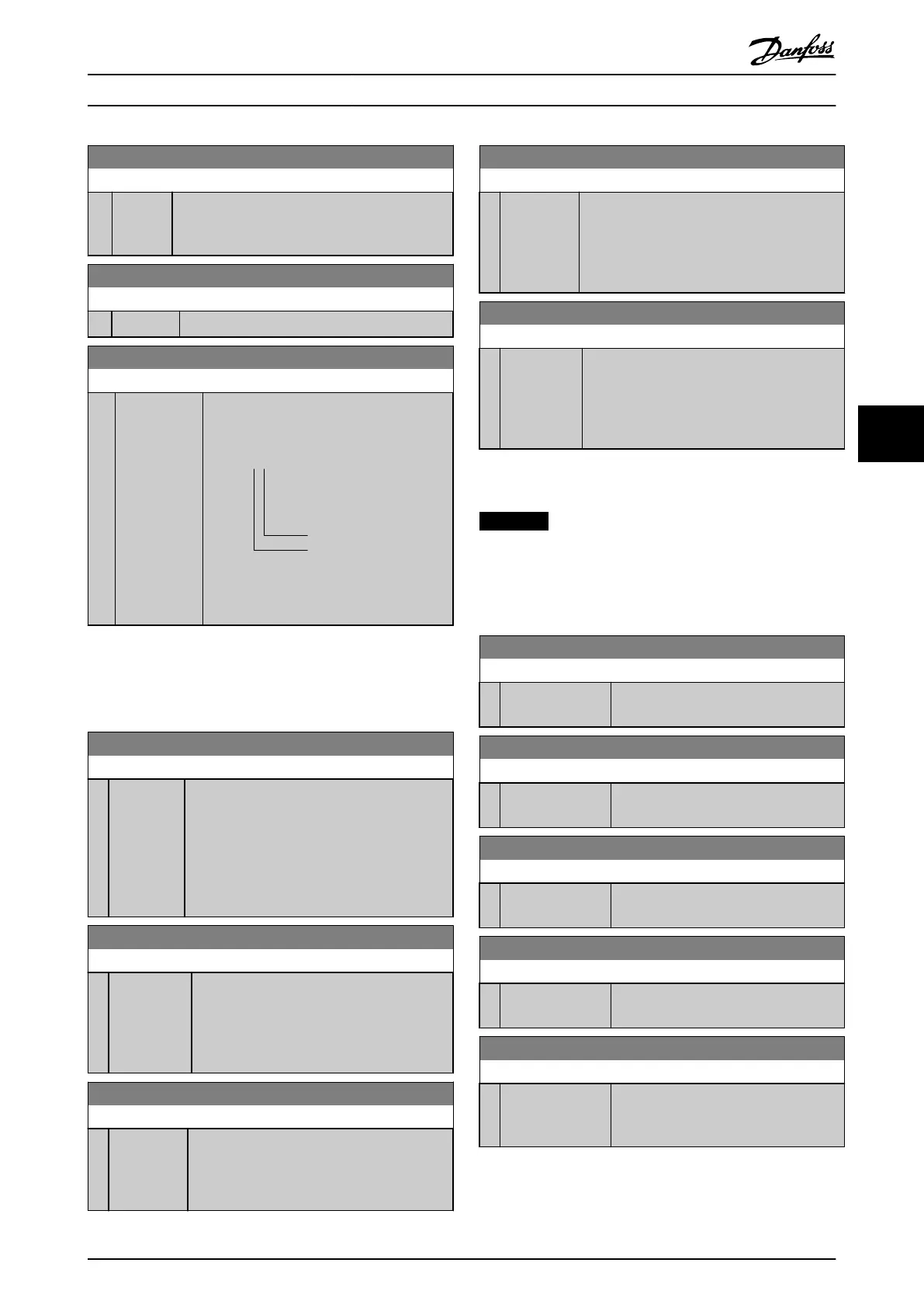
Readout choice (Par. 16-71):
Relay output (bin):
Power card relay 02
Power card relay 01
130BD870.10
0 0 bin
Illustration 6.5 Relay Settings
6.10.4 16-8* Fieldbus & FC Port
Parameters for reporting the BUS references and control
words.
16-80 Fieldbus CTW 1
Range: Function:
0* [0 -
65535 ]
View the 2-byte control word (CTW) received
from the bus master. Interpretation of the
control word depends on the fieldbus option
installed and the control word profile selected
in 8-10 Control Profile.
For more information, refer to the relevant
fieldbus manual.
16-82 Fieldbus REF 1
Range: Function:
0* [-200 - 200 ] View the 2-byte word sent with the control
word from the bus master to set the reference
value.
For more information, refer to the relevant
fieldbus manual.
16-84 Comm. Option STW
Range: Function:
0* [0 - 65535 ] View the extended fieldbus comm. option
status word.
For more information, refer to the relevant
fieldbus manual.
16-85 FC Port CTW 1
Range: Function:
0* [0 - 65535 ] View the 2-byte control word (CTW) received
from the bus master. Interpretation of the
control word depends on the fieldbus option
installed and the control word profile selected
in 8-10 Control Profile.
16-86 FC Port REF 1
Range: Function:
0* [-200 -
200 ]
View the 2-byte status word (STW) sent to the
bus master. Interpretation of the status word
depends on the fieldbus option installed and
the control word profile selected in
8-10 Control Profile.
6.10.5 16-9* Diagnosis Read-Outs
NOTICE
When using MCT 10 Set-up Software, the readout
parameters can only be read online, i.e. as the actual
status. This means that the status is not stored in the
MCT 10 Set-up Software file.
16-90 Alarm Word
Range: Function:
0* [0 - 4294967295 ] View the alarm word sent via the serial
communication port in hex code.
16-91 Alarm Word 2
Range: Function:
0* [0 - 4294967295 ] View the alarm word sent via the serial
communication port in hex code.
16-92 Warning Word
Range: Function:
0* [0 - 4294967295 ] View the warning word sent via the serial
communication port in hex code.
16-93 Warning Word 2
Range: Function:
0* [0 - 4294967295 ] View the warning word sent via the serial
communication port in hex code.
16-94 Ext. Status Word
Range: Function:
0* [0 - 4294967295 ] Returns the extended warning word sent
via the serial communication port in hex
code.
How to Programme Operating Instructions
MG33X402 Danfoss A/S © Rev. 05/2014 All rights reserved. 63
6 6