During the normal operation, the AFE DC-link voltage is
regulated to be constant. This means that the energy from
the decelerated motor is passed on to the mains as
regenerated electrical energy. A passive rectifier would
require a braking resistor to consume the surplus energy
as heat. The AFE is energy efficient for the application
where the motor deceleration is frequent. Also the brake
resistor space is saved.
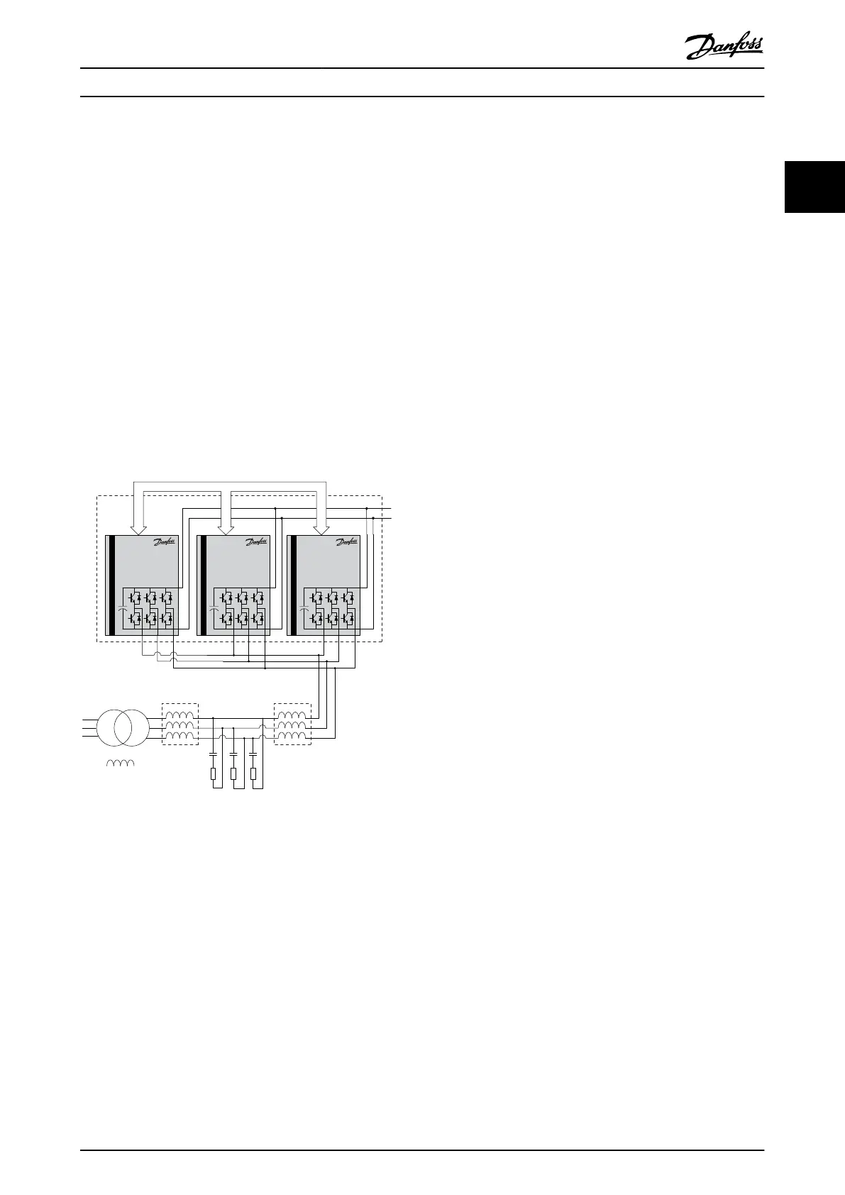
The LCL filter allows the power flow. It also reduces the
ripple current of the fundamental frequency, switching
frequency, and their harmonics into the mains. A damping
resistor Rd is connected in series with the filter capacitor
Cf to stabilize the filter resonance.
The three inverter units are connected in parallel to
achieve the required power level. One AFE controller
regulates the three parallel-connected inverter units.
Transformer
AFE
Master Slave Slave
Control signals
130BA771.11
L
m
L
t
C
f
L
C
R
d
Illustration 2.1 Active Front End System Example
Safety Instructions and Gen... Operating Instructions
MG33X402 Danfoss A/S © Rev. 05/2014 All rights reserved. 7
2 2