Analog input/output terminals
Terminal Parameter Default
setting
Description
53 Parameter
group 6-1*
Analog Input 1
Reference Analog input. For
voltage or current.
Switches A53 and
A54 select mA or V.
54 Parameter
group 6-2*
Analog Input 2
Feedback
55 – – Common for analog
input.
Table 10.9 Analog Input/Output Terminal Descriptions
Relay terminals:
RELAY 1 RELAY 2
01 02 03 04 05 06
130BF156.10
Illustration 10.13 Relay 1 and Relay 2 Terminals
•
Relay 1 and relay 2. The location of the outputs
depends on the drive conguration. See the
operating guide.
•
Terminals on built-in optional equipment. See the
instructions provided with the equipment option.
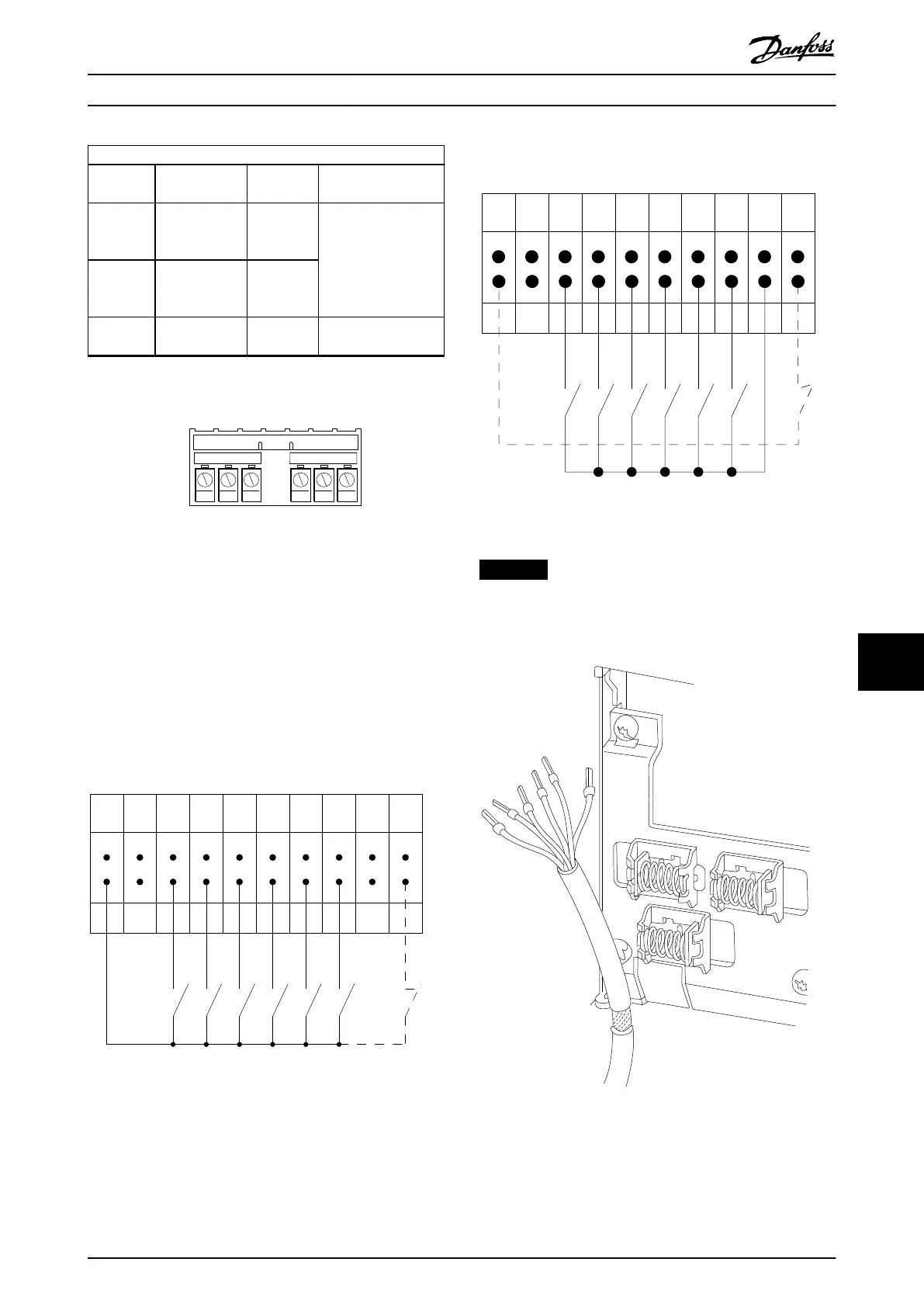
10.4.3 Input Polarity of Control Cables
12 13 18 19 27 29 32 33 20 37
+24 VDC
0 VDC
130BT106.10
PNP (Source)
Digital input wiring
Illustration 10.14 Input Polarity of Control Terminals (PNP
Source)
NPN (Sink)
Digital input wiring
12 13 18 19 27 29 32 33 20 37
+24 VDC
0 VDC
130BT107.11
Illustration 10.15 Input Polarity of Control Terminals (NPN
Sink)
NOTICE
Use shielded cables to comply with EMC emission speci-
cations. For more information, see chapter 10.16 EMC-
compliant Installation.
Illustration 10.16 Shield Termination and Strain Relief of
Control Cable
Electrical Installation Con... Design Guide
MG16C302 Danfoss A/S © 11/2017 All rights reserved. 175
10 10
 Loading...


