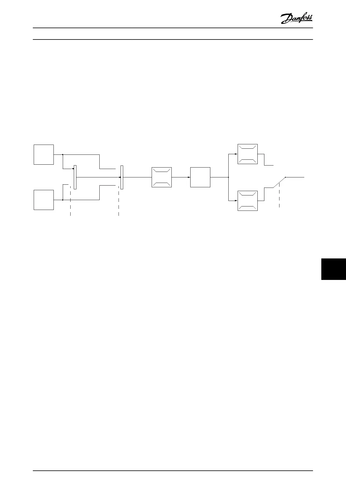
In the conguration shown in Illustration 11.6, the drive operates in open-loop mode. It receives input from either the LCP
(hand-on mode) or via a remote signal (auto-on mode). The signal (speed reference) is received and conditioned with the
following:
•
Programmed minimum and maximum motor speed limits (in RPM and Hz).
•
Ramp-up and ramp-down times.
•
Motor rotation direction.
The reference is then passed on to control the motor.
130BB153.10
100%
0%
-100%
100%
P 3-13
Reference
site
Local
reference
scaled to
RPM or Hz
Auto mode
Hand mode
LCP Hand on,
o and auto
on keys
Linked to hand/auto
Local
Remote
Reference
Ramp
P 4-10
Motor speed
direction
To motor
control
Reference
handling
Remote
reference
P 4-13
Motor speed
high limit [RPM]
P 4-14
Motor speed
high limit [Hz]
P 4-11
Motor speed
low limit [RPM]
P 4-12
Motor speed
low limit [Hz]
P 3-4* Ramp 1
P 3-5* Ramp 2
Illustration 11.6 Block Diagram of an Open-loop Control Structure
11.2.6 Closed-loop Control Structure
In closed-loop mode, the drive uses 1 or more references (local or remote) and feedback sensors to control the motor. The
drive receives a feedback signal from a sensor in the system. It then compares this feedback to a setpoint reference value
and determines if there is any discrepancy between these 2 signals. The drive then adjusts the speed of the motor to
correct the discrepancy.
For example, consider a pump application in which the speed of the pump is controlled so that the static pressure in a pipe
is constant (see Illustration 11.7). The drive receives a feedback signal from a sensor in the system. It compares this feedback
to a setpoint reference value and determines the discrepancy if any, between these 2 signals. It then adjusts the speed of
the motor to compensate for the discrepancy.
The static pressure setpoint is the reference signal to the drive. A static pressure sensor measures the actual static pressure
in the pipe and provides this information to the drive as a feedback signal. If the feedback signal exceeds the setpoint
reference, the drive ramps down to reduce the pressure. Similarly, if the pipe pressure is lower than the setpoint reference,
the drive ramps up to increase the pump pressure.
There are 3 types of closed-loop control:
•
Speed control. This type of control requires a speed PID feedback for an input. A properly optimized speed closed-
loop control has higher accuracy than a speed open-loop control. Speed control is only used in the VLT
®
AutomationDrive.
•
Torque control. Used in ux mode with encoder feedback, this control oers superior performance in all 4
quadrants and at all motor speeds. Torque control is only used in the VLT
®
AutomationDrive.
The torque control function is used in applications where the torque on the motor output shaft is controlling the
application as tension control. Torque setting is done by setting an analog, digital, or bus-controlled reference.
Basic Operating Principles ... Design Guide
MG16C302 Danfoss A/S © 11/2017 All rights reserved. 205
11 11
 Loading...


