Switching frequency:
When adjustable frequency drives are used together with sine-wave filters to reduce the acoustic noise from a motor, the switching frequency must be
set according to the instructions in par. 14-01
Switching Frequency
.
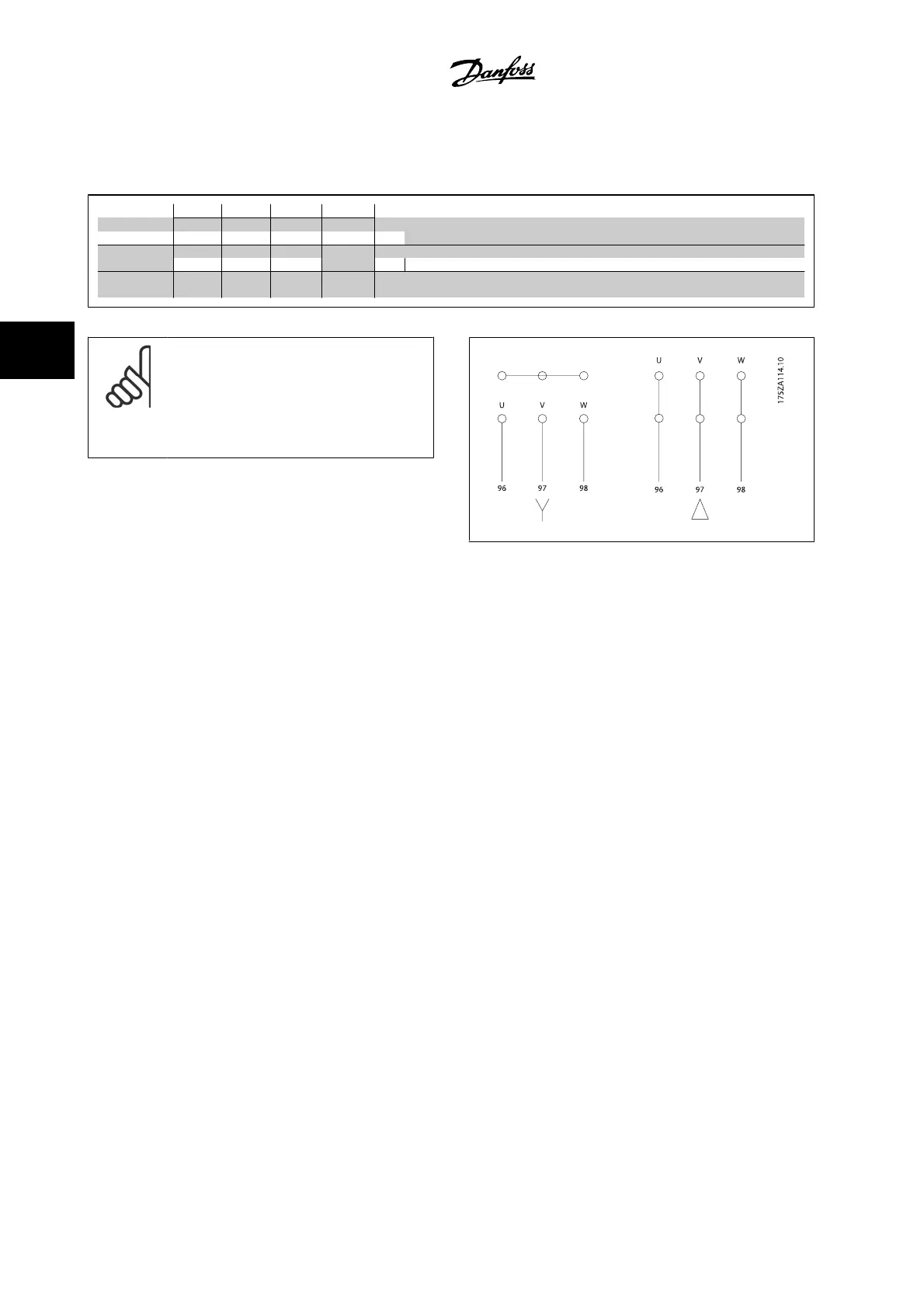
Term. no. 96 97 98 99
U V W
PE
1)
Motor voltage 0–100% of AC line voltage.
3 wires out of motor
U1 V1 W1
PE
1)
Delta-connected
W2 U2 V2 6 wires out of motor
U1 V1 W1
PE
1)
Star-connected U2, V2, W2
U2, V2 and W2 to be interconnected separately.
1)Protected Ground Connection
NOTE!
In motors without phase insulation paper or other in-
sulation reinforcement suitable for operation with volt-
age supply (such as a adjustable frequency drive), fit
a sine-wave filter on the output of the adjustable fre-
quency drive.
4 How to Install
VLT AQUA Low Harmonic Drive Instruction
Manual
4-34
MG.20.T1.22 - VLT
®
is a registered Danfoss trademark
4

 Loading...


