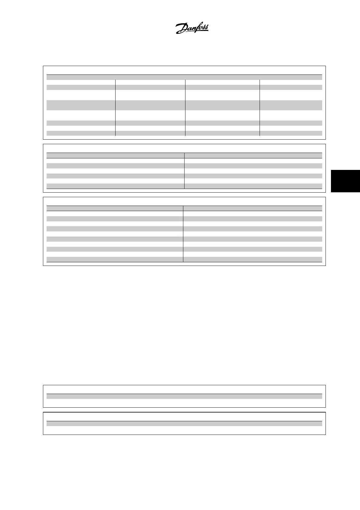
The Function Set-up parameters are grouped in the following way:
Q3-1 General Settings
Q3-10 Clock Settings Q3-11 Display Settings Q3-12 Analog Output Q3-13 Relays
0-70 Set Date and Time 0-20 Display Line 1.1 Small 6-50 Terminal 42 Output Relay 1 ⇒ 5-40 Function Relay
0-71 Date Format 0-21 Display Line 1.2 Small 6-51 Terminal 42 Output Min Scale Relay 2 ⇒ 5-40 Function Relay
0-72 Time Format 0-22 Display Line 1.3 Small 6-52 Terminal 42 Output Max Scale
Option relay 7 ⇒ 5-40 Function
Relay
0-74 DST/Summertime 0-23 Display Line 2 Large Option relay 8 ⇒ 5-40 Function
Relay
0-76 DST/Summertime Start 0-24 Display Line 3 Large Option relay 9 ⇒ 5-40 Function
Relay
0-77 DST/Summertime End 0-37 Display Text 1
0-38 Display Text 2
0-39 Display Text 3
Q3-2 Open-loop Settings
Q3-20 Digital Reference Q3-21 Analog Reference
3-02 Minimum Reference 3-02 Minimum Reference
3-03 Maximum Reference 3-03 Maximum Reference
3-10 Preset Reference 6-10 Terminal 53 Low Voltage
5-13 Terminal 29 Digital Input 6-11 Terminal 53 High Voltage
5-14 Terminal 32 Digital Input 6-14 Terminal 53 Low Ref/Feedb. Value
5-15 Terminal 33 Digital Input 6-15 Terminal 53 High Ref/Feedb. Value
Q3-3 Closed-loop Settings
Q3-30 Feedback Settings Q3-31 PID Settings
1-00 Configuration Mode 20-81 PID Normal/Inverse Control
20-12 Reference/Feedb.Unit 20-82 PID Start Speed [RPM]
3-02 Minimum Reference 20-21 Setpoint 1
3-03 Maximum Reference 20-93 PID Proportional Gain
6-20 Terminal 54 Low Voltage 20-94 PID Integral Time
6-21 Terminal 54 High Voltage
6-24 Terminal 54 Low Ref/Feedb Value
6-25 Terminal 54 High Ref/Feedb Value
6-00 Live Zero Timeout Time
6-01 Live Zero Timeout Function
6.1.6 Q5 Changes Made
Q5 Changes Made can be used for fault finding.
Select
Changes made
to get information about:
• The last 10 changes. Use the up/down navigation keys to scroll between the last 10 changed parameters.
• The changes made since default setting.
Select
Loggings
to get information about the display line readouts. The information is shown in graphs.
Only display parameters selected in par. 0-20 and par. 0-24 can be viewed. It is possible to store up to 120 samples in the memory for later reference.
Please notice that the parameters listed in the below tables for Q5 only serve as examples since they will vary depending on the programming of the
particular adjustable frequency drive.
Q5-1 Last 10 Changes
20-94 PID Integral Time
20-93 PID Proportional Gain
Q5-2 Since Factory Setting
20-93 PID Proportional Gain
20-94 PID Integral Time
VLT AQUA Low Harmonic Drive Instruction
Manual
6 How to Program the Low Harmonic Drive
MG.20.T1.22 - VLT
®
is a registered Danfoss trademark
6-5
6

 Loading...


