Q5-3 Input Assignments
Analog Input 53
Analog Input 54
6.1.7 Q6 Loggings
Q6 Loggings can be used for fault finding.
Please notice that the parameters listed in the table for Q6 below only serve as examples since they will vary depending on the programming of the
particular adjustable frequency drive.
Q6 Loggings
Reference
Analog Input 53
Motor Current
Frequency
Feedback
Energy Log
Trending Cont Bin
Trending Timed Bin
Trending Comparison
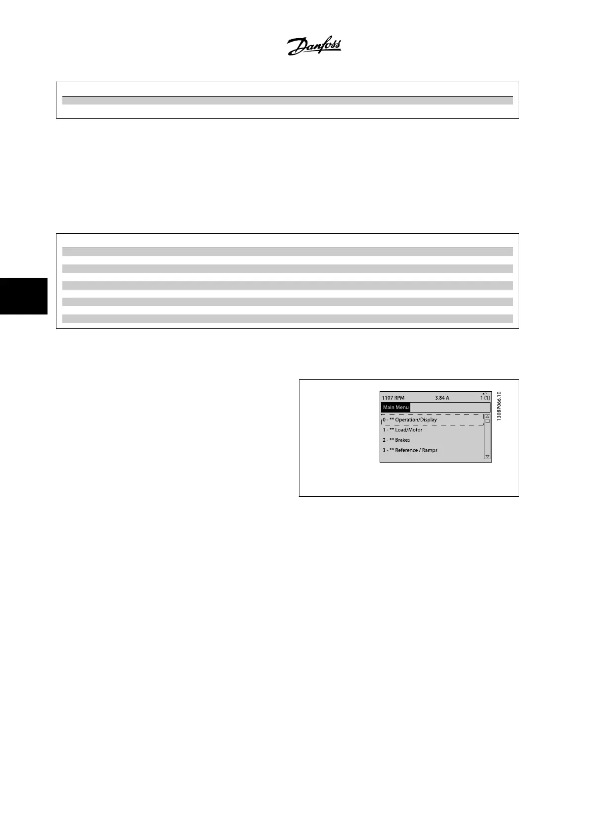
6.1.8 Main Menu Mode
Both the GLCP and NLCP provide access to the main menu mode. Select
main menu mode by pressing the [Main Menu] key. Figure 6.2 shows the
resulting read-out, which appears on the display of the GLCP.
Lines 2 through 5 on the display show a list of parameter groups which
can be chosen by toggling the up and down buttons.
Figure 6.9: Display example.
Each parameter has a name and number which remain the same regardless of the programming mode. In main menu mode, the parameters are divided
into groups. The first digit of the parameter number (from the left) indicates the parameter group number.
All parameters can be changed in the Main Menu. The configuration of the unit (par. 1-00
Configuration Mode
) will determine other parameters available
for programming. For example, selecting Closed-loop enables additional parameters related to closed-loop operation. Option cards added to the unit
enable additional parameters associated with the option device.
6 How to Program the Low Harmonic Drive
VLT AQUA Low Harmonic Drive Instruction
Manual
6-6
MG.20.T1.22 - VLT
®
is a registered Danfoss trademark
6

 Loading...


