6.1.9 Parameter Selection
In main menu mode, the parameters are divided into groups. Select a
parameter group using the navigation keys.
The following parameter groups are accessible:
Group no. Parameter group:
0 Operation/Display
1Load/Motor
2 Brakes
3 References/Ramps
4 Limits/Warnings
5Digital In/Out
6 Analog In/Out
8 Comm. and Options
9 Profibus
10 CAN Fieldbus
11 LonWorks
13 Smart Logic
14 Special Functions
15 Drive Information
16 Data Readouts
18 Data Readouts 2
20 Drive Closed-loop
21 Ext. Closed-loop
22 Application Functions
23 Time-based Functions
24 Fire Mode
25 Cascade Controller
26 Analog I/O Option MCB 109
Table 6.3: Parameter groups.
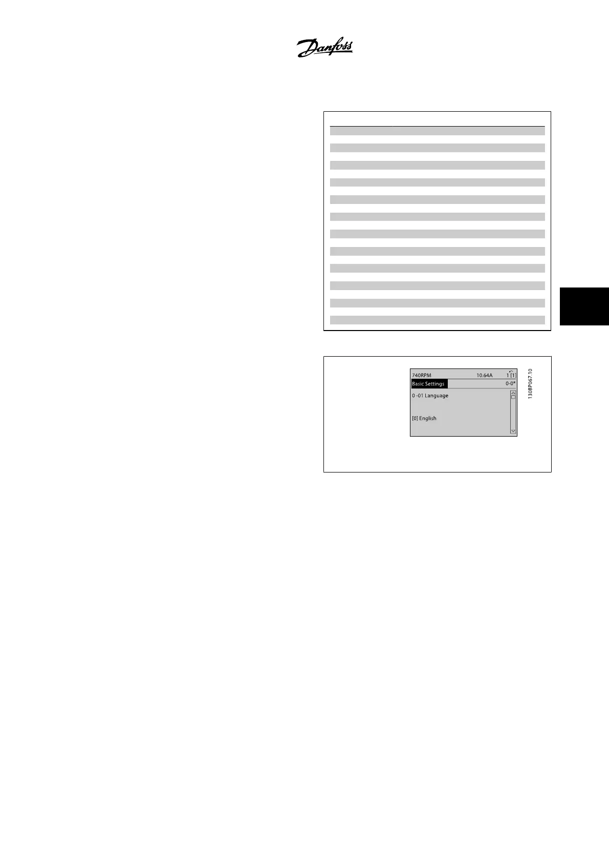
After selecting a parameter group, choose a parameter by means of the
navigation keys.
The middle section on the GLCP display shows the parameter number and
name, as well as the selected parameter value.
Figure 6.10: Display example.
VLT AQUA Low Harmonic Drive Instruction
Manual
6 How to Program the Low Harmonic Drive
MG.20.T1.22 - VLT
®
is a registered Danfoss trademark
6-7
6
 Loading...


