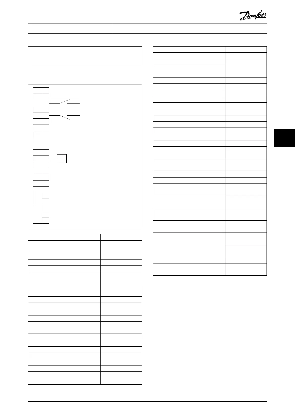
Application
One Gear Drive (OGD) LA10.
Parameter 0-16 Application Selection is set to [6] OGD LA10.
Description
For applications that use OGD. For example, conveyors in food
and beverage industries.
+24V 12
DI1 18
DI2 19
DI3 27
DI4 29
DI5 3
2DI6 3
3DI7 3
1
COM 20
+10V 50
AI1
53
-
+
AI2
54
COM 55
AO1
45AO2
42
1
2
3
4
5
6
R1
R2
FC 360
Start
Coast inverse
4-20
mA
130BD898.11
Parameter settings
Parameter Option/value
Parameter 1-00 Conguration Mode [0] Open Loop
Parameter 1-01 Motor Control Principle [1] VVC+
Parameter 1-08 Motor Control Bandwidth High
Parameter 1-10 Motor Construction [1] PM, non-salient SPM
Parameter 1-14 Damping Gain 120
Parameter 1-15 Low Speed Filter Time
Const.
0.175
Parameter 1-16 High Speed Filter Time
Const.
0.175
Parameter 1-17 Voltage lter time const. 0.035
Parameter 1-24 Motor Current 7.2
Parameter 1-25 Motor Nominal Speed 3000
Parameter 1-26 Motor Cont. Rated Torque 12.6
Parameter 1-29 Automatic Motor
Adaptation (AMA)
[0] O
Parameter 1-30 Stator Resistance (Rs) 0.5
Parameter 1-37 d-axis Inductance (Ld) 5
Parameter 1-39 Motor Poles 10
Parameter 1-40 Back EMF at 1000 RPM 120
Parameter 1-42 Motor Cable Length 50 m
Parameter 1-66 Min. Current at Low Speed 50
Parameter 1-73 Flying Start [2] Enable always
Parameter 2-06 Parking Current 80
Parameter 2-07 Parking Time 0.5
Parameter 2-10 Brake Function [0] O
Parameter 3-03 Maximum Reference 250 Hz
Parameter 4-14 Motor Speed High Limit
[Hz]
250 Hz
Parameter 4-16 Torque Limit Motor Mode 160
Parameter 4-18 Current Limit 160
Parameter 5-10 Terminal 18 Digital Input [8] Start
Parameter 5-11 Terminal 19 Digital Input [0] No operation
Parameter 5-12 Terminal 27 Digital Input [2] Coast inverse
Parameter 5-13 Terminal 29 Digital Input [0] No operation
Parameter 5-14 Terminal 32 Digital Input [0] No operation
Parameter 5-15 Terminal 33 Digital Input [0] No operation
Parameter 5-16 Terminal 31 Digital Input [0] No operation
Parameter 6-10 Terminal 53 Low Voltage 4.0 mA
Parameter 6-11 Terminal 53 High Voltage 20.0 mA
Parameter 6-14 Terminal 53 Low Ref./
Feedb. Value
0
Parameter 6-15 Terminal 53 High Ref./
Feedb. Value
250
Parameter 6-19 Terminal 53 mode [0] Current Mode
Parameter 14-01 Switching Frequency 10.0 kHz
Parameter 14-07 Dead Time Compen-
sation Level
65
Parameter 14-64 Dead Time Compen-
sation Zero Current Level
[0] Disabled
Parameter 14-65 Speed Derate Dead Time
Compensation
250
Parameter 14-51 DC-Link Voltage Compen-
sation
[0] O
Parameter 30-20 High Starting Torque
Time [s]
0
Parameter 30-21 High Starting Torque
Current [%]
100
Parameter 30-22 Locked Rotor Protection [0] O
Parameter 30-23 Locked Rotor Detection
Time [s]
1
Table 6.6 One Gear Drive (OGD) LA10
Applications Quick Guide
MG06A702 Danfoss A/S © 03/2017 All rights reserved. 41
6
6

 Loading...


