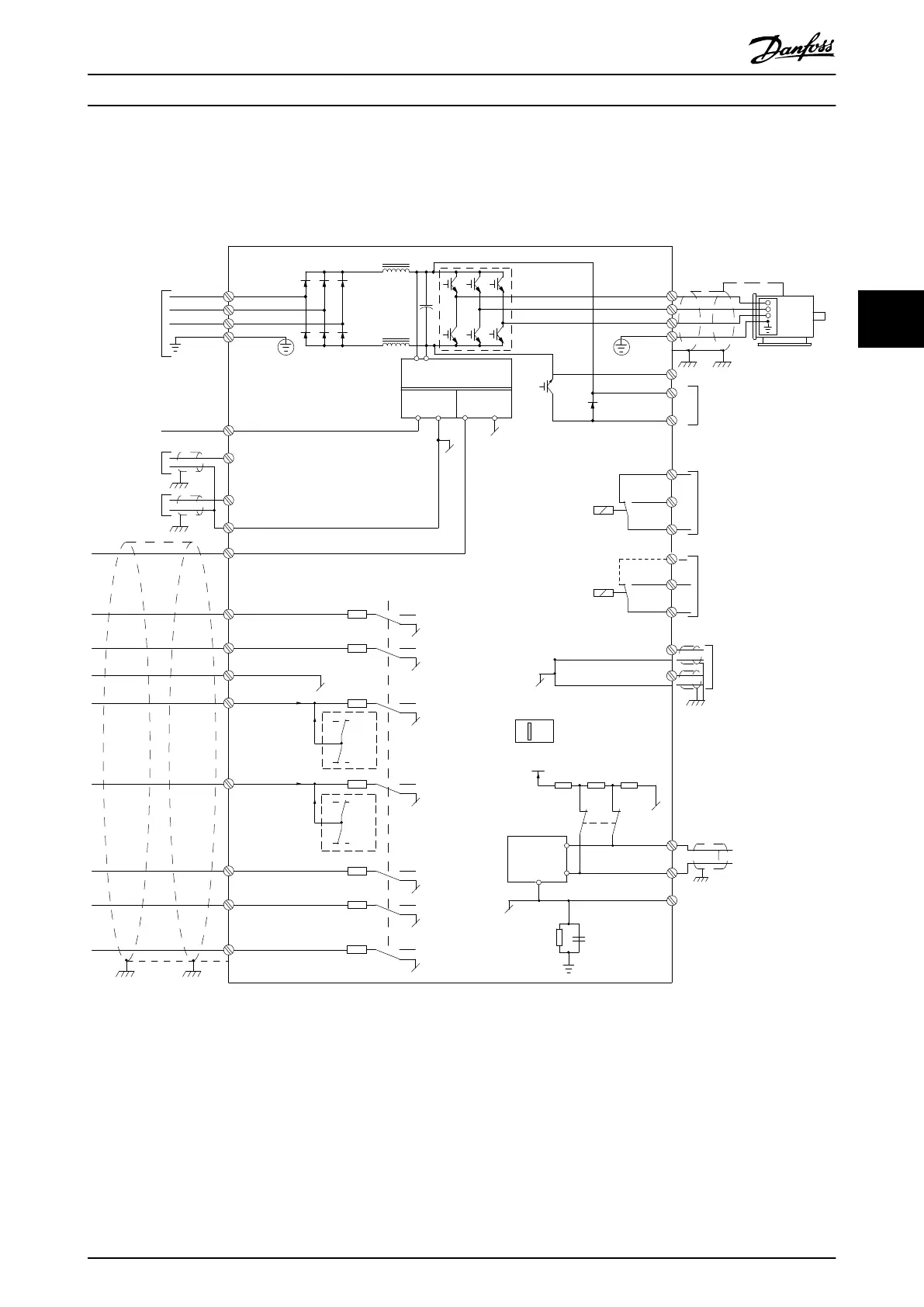
4.4 Wiring Schematic
This section describes how to wire the frequency converter.
130BC438.17
3 phase
power
input
Switch Mode
Power Supply
Motor
Analog Output
Interface
(PNP) = Source
(NPN) = Sink
ON=Terminated
OFF=Open
Brake
resistor
91 (L1)
92 (L2)
93 (L3)
PE
50 (+10 V OUT)
53 (A IN)
54 (A IN)
55 (COM A IN)
0/4-20 mA
12 (+24 V OUT)
31 (D IN)
18 (D IN)
20 (COM D IN)
10 V DC
15 mA 100 mA
+ - + -
(U) 96
(V) 97
(W) 98
(PE) 99
(A OUT) 45
(A OUT) 42
(P RS485) 68
(N RS485) 69
(COM RS485) 61
0V
5V
S801
0/4-20 mA
RS485
RS485
03
+10 V DC
0/4-20 mA
0-10 V DC
24 V DC
02
01
05
04
250 V AC, 3 A
24 V (NPN)
0 V (PNP)
0 V (PNP)
24 V (NPN)
19 (D IN)
24 V (NPN)
0 V (PNP)
27 (D IN/OUT)
24 V
0 V
0 V (PNP)
24 V (NPN)
0 V
24 V
29 (D IN/OUT)
24 V (NPN)
0 V (PNP)
0 V (PNP)
24 V (NPN)
33 (D IN)
32 (D IN)
95
P 5-00
21
ON
(+UDC) 89
(BR) 81 5)
24 V (NPN)
0 V (PNP)
0-10 V DC
(-UDC) 88
RFI
3)
0 V
250 V AC, 3 A
Relay 1
1)
Relay 2 2)
4)
06
Illustration 4.2 Basic Wiring Schematic Drawing
A=Analog, D=Digital
1) Built-in brake chopper available from J1–J5.
2) Relay 2 is 2-pole for J1–J3 and 3-pole for J4–J7. Relay 2 of J4–J7 with terminals 4, 5, and 6 has same NO/NC logic as relay 1.
Relays are pluggable in J1–J5, and xed in J6–J7.
3) Single DC choke in J1–J5; Dual DC choke in J6–J7.
4) Switch S801 (bus terminal) can be used to enable termination on the RS485 port (terminals 68 and 69).
5) No BR for J6–J7.
Electrical Installation Quick Guide
MG06A702 Danfoss A/S © 03/2017 All rights reserved. 15
4 4

 Loading...


