4.6 Control Wiring
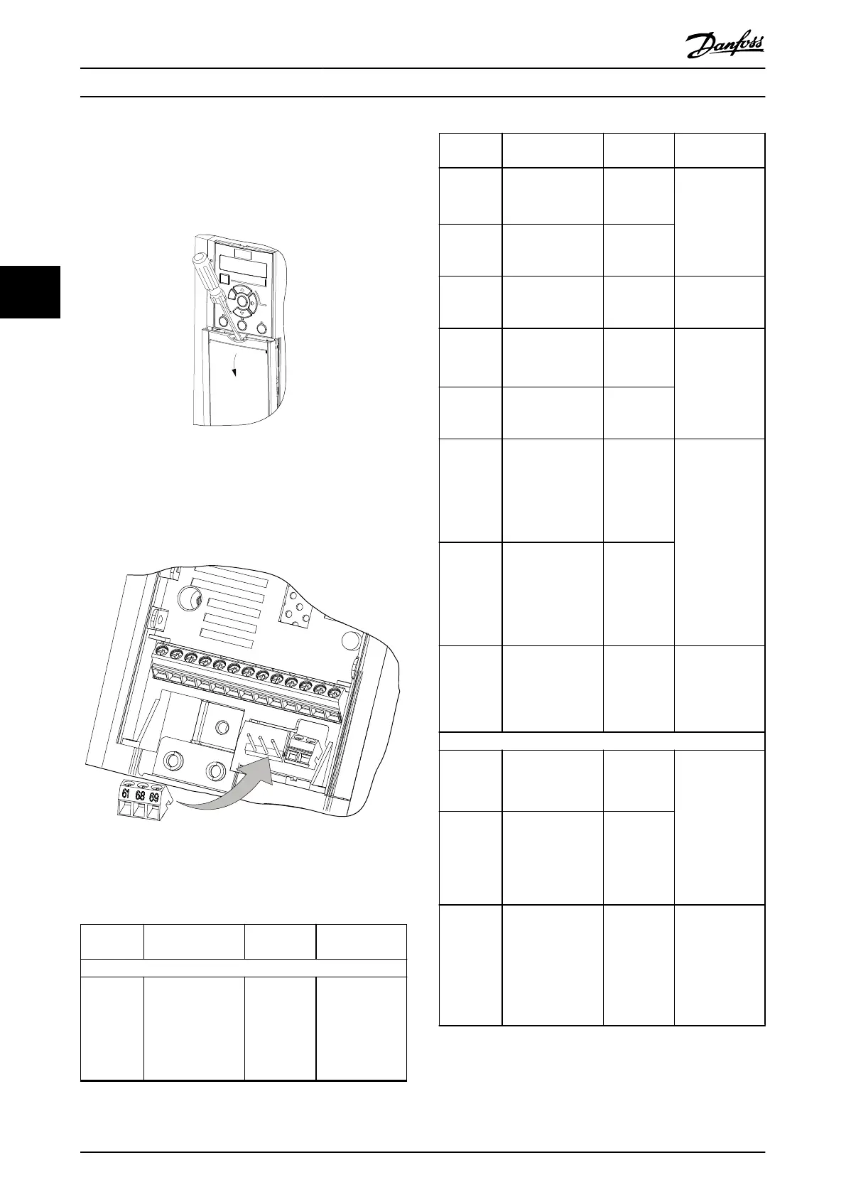
Access
•
Remove the cover plate with a screwdriver. See
Illustration 4.6.
Illustration 4.6 Control Wiring Access for Enclosure Sizes J1–J7
Control terminal types
Illustration 4.7 shows the frequency converter control
terminals. Terminal functions and default settings are
summarized in Table 4.1.
42 45
12
18
19
27
29
31
32
33
20
50
53
54
55
Illustration 4.7 Control Terminal Locations
See chapter 8.2 General Technical Data for terminal ratings
details.
Terminal Parameter
Default
setting
Description
Digital I/O, pulse I/O, encoder
12 – +24 V DC
24 V DC supply
voltage.
Maximum
output current is
100 mA for all
24 V loads.
Terminal Parameter
Default
setting
Description
18
Parameter 5-10 Ter
minal 18 Digital
Input
[8] Start
Digital inputs.
19
Parameter 5-11 Ter
minal 19 Digital
Input
[10]
Reversing
31
Parameter 5-16 Ter
minal 31 Digital
Input
[0] No
operation
Digital input.
32
Parameter 5-14 Ter
minal 32 Digital
Input
[0] No
operation
Digital input, 24
V encoder.
Terminal 33 can
be used for
pulse input.
33
Parameter 5-15 Ter
minal 33 Digital
Input
[16] Preset ref
bit 0
27
Parameter 5-12 Ter
minal 27 Digital
Input
parameter 5-30 Ter
minal 27 Digital
Output
DI [2] Coast
inverse
DO [0] No
operation
Selectable for
either digital
input, digital
output, or pulse
output. Default
setting is digital
input.
Terminal 29 can
be used for
pulse input.
29
Parameter 5-13 Ter
minal 29 Digital
Input
parameter 5-31 Ter
minal 29 Digital
Output
DI [14] Jog
DO [0] No
operation
20 – –
Common for
digital inputs
and 0 V
potential for 24
V supply.
Analog inputs/outputs
42
Parameter 6-91 Ter
minal 42 Analog
Output
[0] No
operation
Programmable
analog output.
The analog
signal is 0–20
mA or 4–20 mA
at a maximum of
500 Ω. Can also
be congured as
digital outputs
45
Parameter 6-71 Ter
minal 45 Analog
Output
[0] No
operation
50 – +10 V DC
10 V DC analog
supply voltage.
15 mA maximum
commonly used
for potenti-
ometer or
thermistor.
Electrical Installation
VLT
®
AutomationDrive FC 360
18 Danfoss A/S © 03/2017 All rights reserved. MG06A702
44

 Loading...


