3.2 Installation Environment
NOTICE
REDUCED LIFETIME
In environments with airborne liquids, particles, or
corrosive gases, ensure that the IP/Type rating of the
equipment matches the installation environment. Failure
to meet requirements for ambient conditions can reduce
lifetime of the frequency converter.
•
Ensure that requirements for air humidity,
temperature, and altitude are met.
Vibration and shock
The frequency converter complies with requirements for
units mounted on the walls and oors of production
premises, and in panels bolted to walls or oors.
For detailed ambient conditions specications, refer to
chapter 8.2 General Technical Data.
3.3 Mounting
Select the best possible operation site by considering:
•
Ambient operating temperature.
•
Installation method.
•
Cooling.
•
Position of the frequency converter.
•
Cable routing.
•
Power source supplying correct voltage and
necessary current.
•
Motor current rating within the maximum current
from the frequency converter.
•
Correct rating of external fuses and circuit
breakers.
Cooling and mounting:
•
Provide top and bottom clearance for air cooling,
see Table 3.2 for clearance requirements.
•
Consider derating for temperatures starting from
45 °C (113 °F) and elevation 1000 m (3281 ft)
above sea level. See the design guide for details
on derating.
Enclosure size
J1–J5 J6 and J7
Clearance above and below the
unit [mm (in)]
100 (3.94) 200 (7.87)
Table 3.2 Minimum Airow Clearance Requirements
•
Mount the unit vertically.
•
IP20 units allow side-by-side installation.
•
Improper mounting can result in overheating and
reduced performance.
•
Use the slotted mounting holes on the unit for
wall mount, when provided.
•
See chapter 8.4 Connection Tightening Torques for
proper tightening specications.
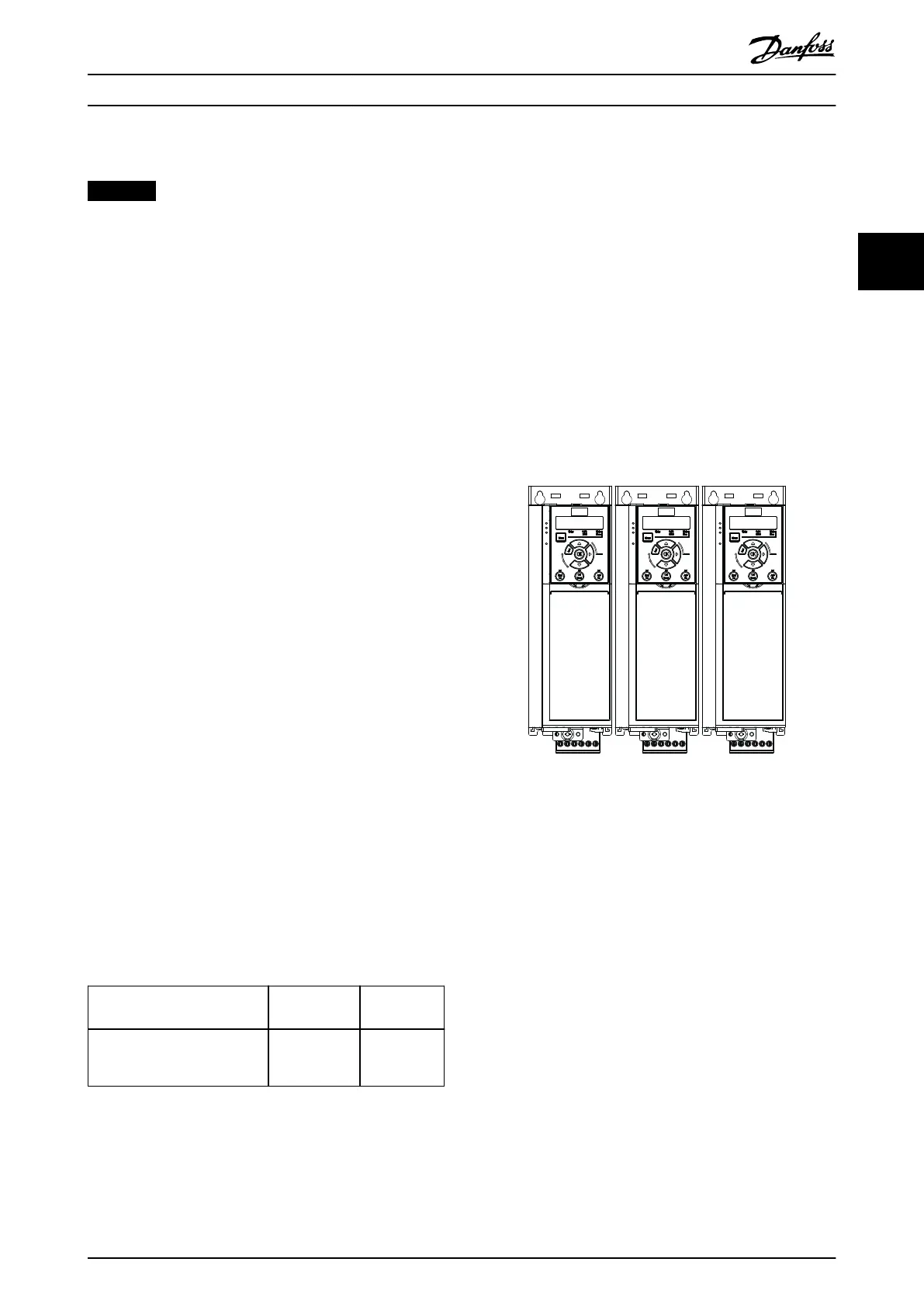
3.3.1 Side-by-side Installation
All VLT
®
AutomationDrive FC 360 units can be installed
side by side in vertical position. The units do not require
extra ventilation on the side.
Illustration 3.3 Side-by-side Installation
Mechanical Installation Quick Guide
MG06A702 Danfoss A/S © 03/2017 All rights reserved. 11
3 3

 Loading...


