4.5 Mains, Motor, and Ground Connections
WARNING
INDUCED VOLTAGE
Run output motor cables from multiple frequency
converters separately. Induced voltage from output
motor cables run together can charge equipment
capacitors even when the equipment is turned o and
locked out. Failure to run output motor cables separately
could result in death or serious injury.
Grounding clamps are provided for motor wiring (see
Illustration 4.4).
•
Do not install power factor correction capacitors
between the frequency converter and the motor.
•
Do not wire a starting or pole-changing device
between the frequency converter and the motor.
•
Follow motor manufacturer wiring requirements.
•
All frequency converters must be used with an
isolated input source and with ground reference
power lines. When supplied from an isolated
mains source (IT mains or oating delta) or
TT/TN-S mains with a grounded leg (grounded
delta), set parameter 14-50 RFI Filter to OFF
(enclosure sizes J6–J7) or remove the RFI screw
(enclosure sizes J1–J5). When o, the internal RFI
lter capacitors between the chassis and the
intermediate circuit are isolated to avoid damage
to the intermediate circuit and reduce ground
capacity currents in accordance with IEC 61800-3.
•
Do not install a switch between the frequency
converter and the motor in IT mains.
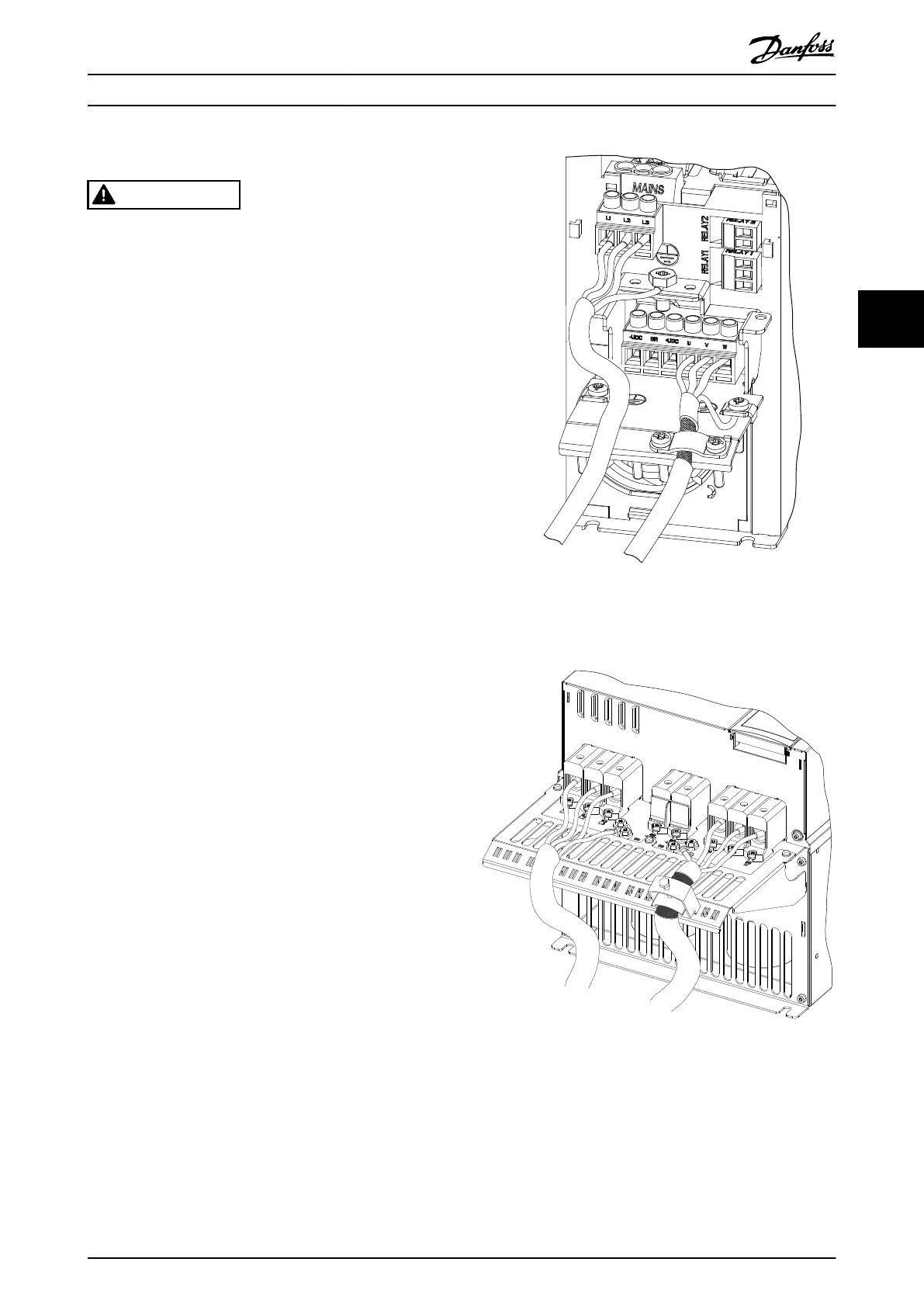
Illustration 4.4 Mains, Motor, and Ground Connections for
Enclosure Sizes J1–J5 (Taking J2 as an example)
Illustration 4.5 Mains, Motor, and Ground Connections for
Enclosure Size J6–J7 (Taking J7 as an example)
Illustration 4.4 shows mains input, motor, and grounding
for enclosure sizes J1–J5. Illustration 4.5 shows mains input,
motor, and grounding for enclosure size J6–J7. Actual
congurations vary with unit types and optional
equipment.
Electrical Installation Quick Guide
MG06A702 Danfoss A/S © 03/2017 All rights reserved. 17
4 4

 Loading...


