Terminal Parameter
Default
setting
Description
53
Parameter group
6-1* Analog Input
53
–
Analog input.
Selectable for
voltage or
current.
54
Parameter group
6-2* Analog Input
54
–
55 – –
Common for
analog input
Serial communication
61 – –
Integrated RC-
lter for cable
shield. ONLY for
connecting the
shield when
experiencing
EMC problems.
68 (+)
Parameter group
8-3* FC Port
Settings
–
RS485 interface.
A control card
switch is
provided for
termination
resistance.
69 (-)
Parameter group
8-3* FC Port
Settings
–
Relays
01, 02, 03 5-40 [0] [9] Alarm
Form C relay
output. These
relays are in
various locations
depending on
the frequency
converter cong-
uration and size.
Usable for AC or
DC voltage and
resistive or
inductive loads.
RO2 in J1–J3
enclosure is 2-
pole, only
terminals 04 and
05 are available
04, 05, 06 5–40 [1] [5] Running
Table 4.1 Terminal Descriptions
Control terminal functions
Frequency converter functions are commanded by
receiving control input signals.
•
Program each terminal for the function it
supports in the parameters associated with that
terminal.
•
Conrm that the control terminal is programmed
for the correct function. See chapter 5 Commis-
sioning for details on accessing parameters and
programming.
•
The default terminal programming initiates
frequency converter functioning in a typical
operational mode.
Using shielded control cables
The preferred method in most cases is to secure control
and serial communication cables with shielding clamps
provided at both ends to ensure the best possible high
frequency cable contact.
If the ground potential between the frequency converter
and the PLC is dierent, electric noise could disturb the
entire system. Solve this problem by tting an equalizing
cable as close as possible to the control cable. Minimum
cable cross-section: 16 mm
2
(6 AWG).
1
2
PE
FC
PE
PLC
130BB922.12
PE PE
<10 mm
1
Minimum 16 mm
2
(6 AWG)
2 Equalizing cable
Illustration 4.8 Shielding Clamps at Both Ends
50/60 Hz ground loops
With long control cables, ground loops could occur. To
eliminate ground loops, connect 1 end of the shield to the
ground with a 100 nF capacitor (keeping leads short).
100nF
FC
PE
PE
PLC
<10 mm
130BB609.12
Illustration 4.9 Connection with a 100 nF Capacitor
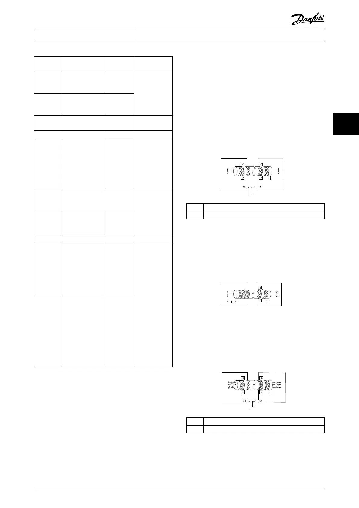
Avoid EMC noise on serial communication
This terminal is connected to ground via an internal RC
link. Use twisted-pair cables to reduce interference
between conductors. The recommended method is shown
in Illustration 4.10.
PE
FC
PE
FC
130BB923.12
PE PE
69
68
61
69
68
61
1
2
<10 mm
1
Minimum 16 mm
2
(6 AWG)
2 Equalizing cable
Illustration 4.10 Twisted-pair Cables
Alternatively, the connection to terminal 61 can be
omitted.
Electrical Installation Quick Guide
MG06A702 Danfoss A/S © 03/2017 All rights reserved. 19
4 4

 Loading...


