EasyManuals Logo

Danfoss VLT AutomationDrive FC 361 User Manual

Danfoss VLT AutomationDrive FC 361
82 pages
To Next Page IconTo Next Page
To Previous Page IconTo Previous Page
Page #10 background image
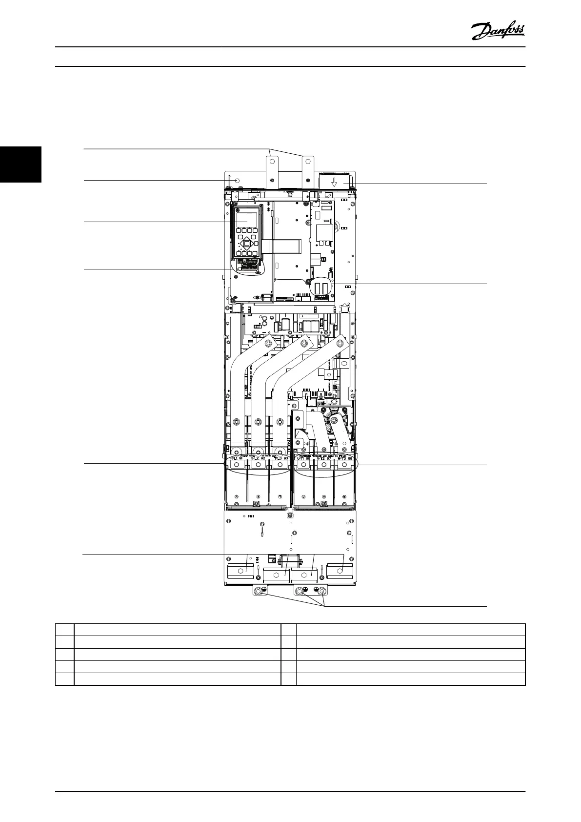
3.4 Interior View of J9 Drive
Illustration 3.2 shows the J9 components relevant to installation and commissioning.
2
3
1
4
5
7
8
9
10
e30bg479.10
6
1 Regen terminals 6 Cable clamps
2 Mounting hole 7 Top fan
3 LCP (local control panel) 8 Relays 1 and 2
4 Control terminals 9 Motor output terminals 96 (U), 97 (V), 98 (W)
5 Mains input terminals 91 (L1), 92 (L2), 93 (L3) 10 Ground terminals
Illustration 3.2 Interior View of J9 Drive
Product Overview VLT® AutomationDrive FC 361
8 Danfoss A/S © 06/2018 All rights reserved. MG06I102
33

Table of Contents

Other manuals for Danfoss VLT AutomationDrive FC 361

Questions and Answers:

Question and Answer IconNeed help?

Do you have a question about the Danfoss VLT AutomationDrive FC 361 and is the answer not in the manual?

Danfoss VLT AutomationDrive FC 361 Specifications

General IconGeneral
BrandDanfoss
ModelVLT AutomationDrive FC 361
CategoryDC Drives
LanguageEnglish

Related product manuals