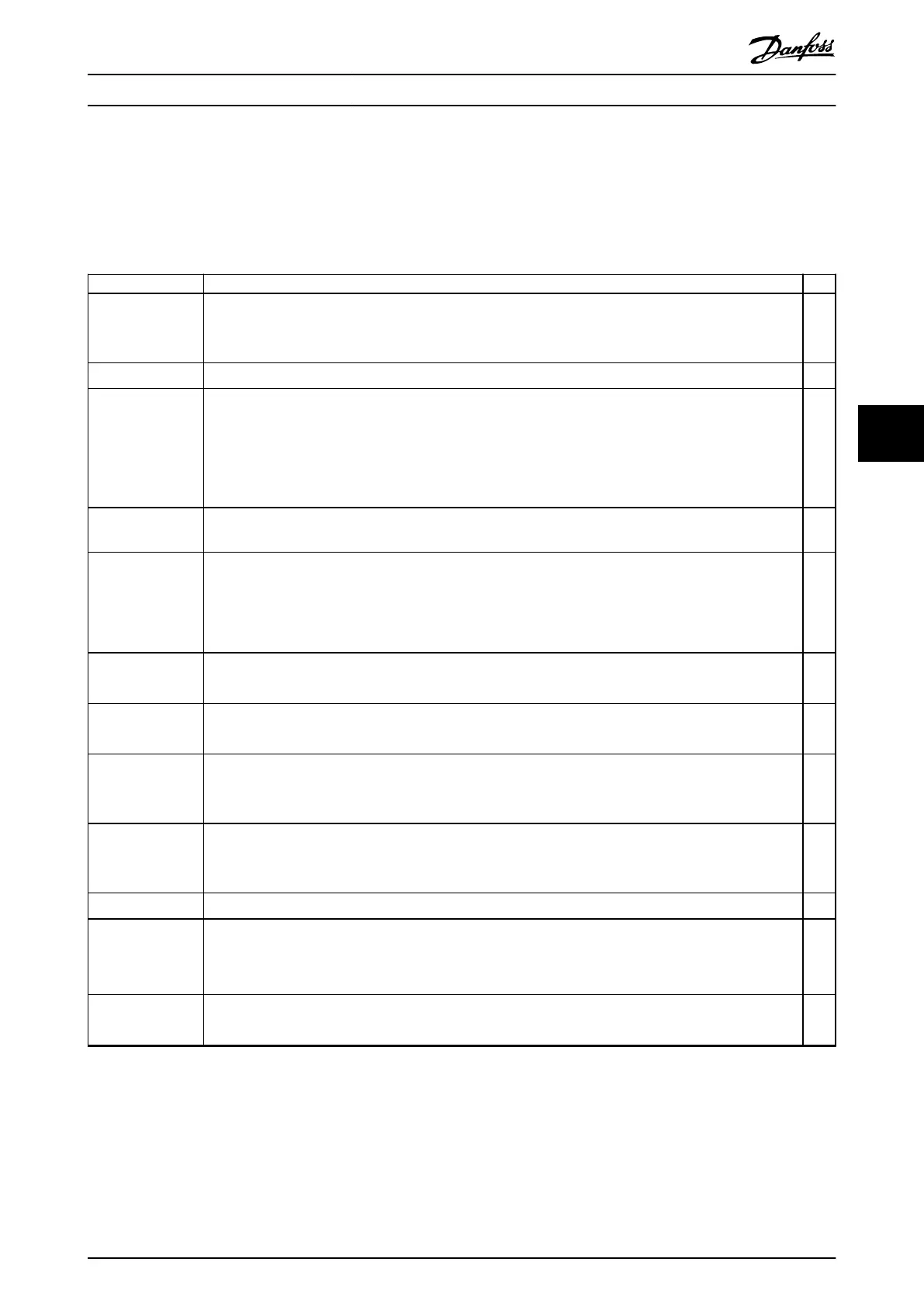
6 Pre-start Check List
Before completing installation of the unit, inspect the entire installation as detailed in Table 6.1. Check and mark the items
when completed.
Inspect for Description
☑
Motor
•
Conrm continuity of the motor by measuring ohm values on U–V (96–97), V–W (97–98), and W– U (98–
96).
•
Conrm that the supply voltage matches the voltage of the drive and the motor.
Switches
•
Ensure that all switch and disconnect settings are in the proper positions.
Auxiliary equipment
•
Look for auxiliary equipment, switches, disconnects, or input fuses/circuit breakers that reside on the input
power side of the drive or output side to the motor. Ensure that they are ready for full-speed operation.
•
Check function and installation of any sensors used for feedback to the drive.
•
Remove any power factor correction caps on motor.
•
Adjust any power factor correction caps on the mains side and ensure that they are dampened.
Cable routing
•
Ensure that motor wiring, brake wiring (if equipped), and control wiring are separated or shielded, or in 3
separate metallic conduits for high-frequency interference isolation.
Control wiring
•
Check for broken or damaged wires and loose connections.
•
Check that control wiring is isolated from high-power wiring for noise immunity.
•
Check the voltage source of the signals, if necessary.
•
Use shielded cable or twisted pair and ensure that the shield is terminated correctly.
Input and output
power wiring
•
Check for loose connections.
•
Check that motor and mains are in separate conduit or separated shielded cables.
Grounding
•
Check for good ground connections that are tight and free of oxidation.
•
Grounding to conduit, or mounting the back panel to a metal surface, is not a suitable grounding.
Fuses and circuit
breakers
•
Check for proper fusing or circuit breakers.
•
Check that all fuses are inserted rmly and are in operational condition and that all circuit breakers (if
used) are in the open position.
Cooling clearance
•
Look for any obstructions in the airow path.
•
Measure top and bottom clearance of the drive to verify adequate airow for cooling, see
chapter 4.5 Installation and Cooling Requirements.
Ambient conditions
•
Check that requirements for ambient conditions are met. See chapter 10.4 Ambient Conditions.
Interior of Drive
•
Inspect that the unit interior is free of dirt, metal chips, moisture, and corrosion.
•
Verify that all installation tools have been removed from unit interior.
•
Ensure that the unit is mounted on an unpainted, metal surface.
Vibration
•
Check that the unit is mounted solidly, or that shock mounts are used, if necessary.
•
Check for an unusual amount of vibration.
Table 6.1 Pre-start Check List
Pre-start Check List Operating Guide
MG06I102 Danfoss A/S © 06/2018 All rights reserved. 35
6
6

 Loading...


