4.7 Mounting the Drive
Wall mounting
J8 and J9 are chassis drives intended to be mounted on a
wall or on a mounting plate within an enclosure. To wall
mount a drive, use the following steps. Refer to
Illustration 4.3.
1. Fasten 2 M10 bolts in the wall to align with the
fastener slots at the bottom of drive.
2. Slide the lower fastener slots in the drive over the
M10 bolts.
3. Tip the drive against the wall, and secure the top
with 2 M10 bolts in the mounting holes.
1 Top mounting holes
2 Lower fastener slots
Illustration 4.3 Drive-to-wall Mounting Holes
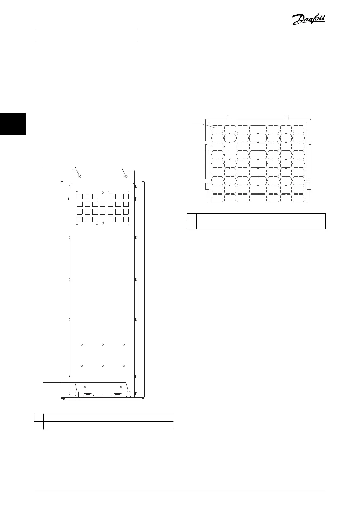
Creating cable openings
After installing the drive, create cable openings in the
gland plate to accommodate the mains and motor cables.
The gland plate is required to maintain the drive
protection rating.
•
Punch out plastic tabs to accommodate the
cables. See Illustration 4.4.
1 Plastic tabs
2 Tabs removed for cable access
Illustration 4.4 Cable Openings in Plastic Gland Plate
Mechanical Installation VLT® AutomationDrive FC 361
16 Danfoss A/S © 06/2018 All rights reserved. MG06I102
44

 Loading...


