The drive uses back-channel cooling to circulate the heat
sink cooling air. The cooling duct can carries approximately
90% of the heat out of the back channel of the drive.
Redirect the back-channel air from the panel or room by
using:
•
Duct cooling. Back-channel cooling kits are
available to direct the air away from the panel
when an IP20/chassis drive is installed in a Rittal
enclosure. Use of a kit reduces the heat in the
panel and smaller door fans can be specied on
the enclosure.
•
Cooling out the back (top and base covers). The
back-channel cooling air can be ventilated out of
the room so that the heat from the back channel
is not dissipated into the control room.
NOTICE
One or more door fans are required on the enclosure to
remove heat not contained in the back channel of the
drive. The fans also remove any additional losses
generated by other components inside the drive.
Ensure that the fans supply adequate airow over the heat
sink. To select the appropriate number of fans, calculate
the total required airow. The ow rate is shown in
Table 4.2.
Enclosure size Door fan/top fan Heat sink fan
J8
102 m
3
/hr (60 CFM) 420 m
3
/hr (250 CFM)
J9
204 m
3
/hr (120 CFM) 840 m
3
/hr (500 CFM)
Table 4.2 Airow
4.6
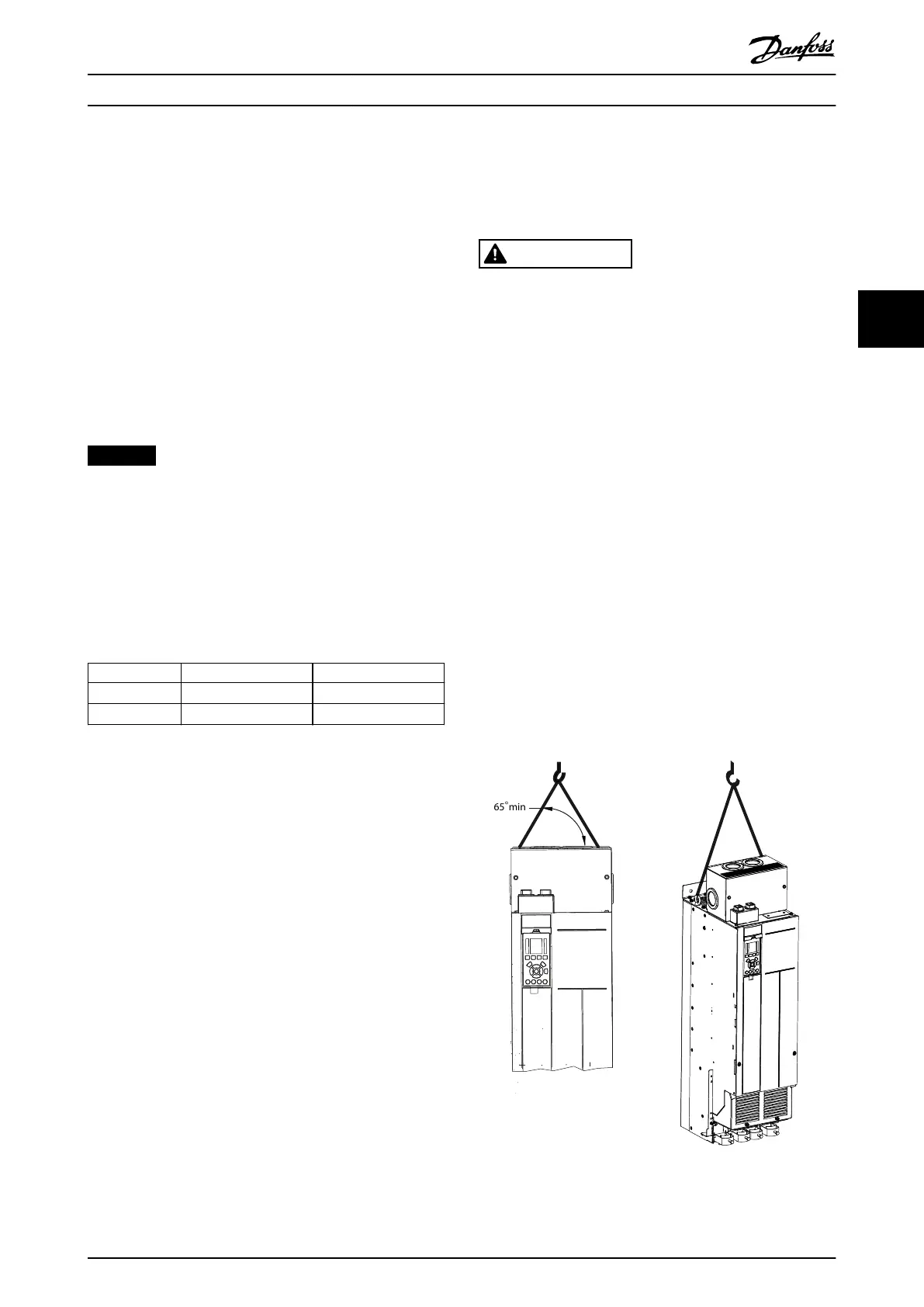
Lifting the Drive
Always lift the drive using the dedicated eye bolts at the
top of the drive. See Illustration 4.2.
WARNING
HEAVY LOAD
Unbalanced loads can fall or tip over. Failure to take
proper lifting precautions increases risk of death, serious
injury, or equipment damage.
•
Move the unit using a hoist, crane, forklift, or
other lifting device with the appropriate weight
rating. See chapter 3.2 Power Ratings, Weights,
and Dimensions for the weight of the drive.
•
Failure to locate the center of gravity and
correctly position the load can cause
unexpected shifting during lifting and
transport. For measurements and center of
gravity, see chapter 10.9 Enclosure Dimensions.
•
The angle from the top of the drive module to
the lifting cables aects the maximum load
force on the cable. This angle must be 65° or
greater. Refer to Illustration 4.2. Attach and
dimension the lifting cables properly.
•
Never walk under suspended loads.
•
To guard against injury, wear personal
protective equipment such as gloves, safety
glasses, and safety shoes.
Illustration 4.2 Lifting the Drive
Mechanical Installation Operating Guide
MG06I102 Danfoss A/S © 06/2018 All rights reserved. 15
4 4
 Loading...


