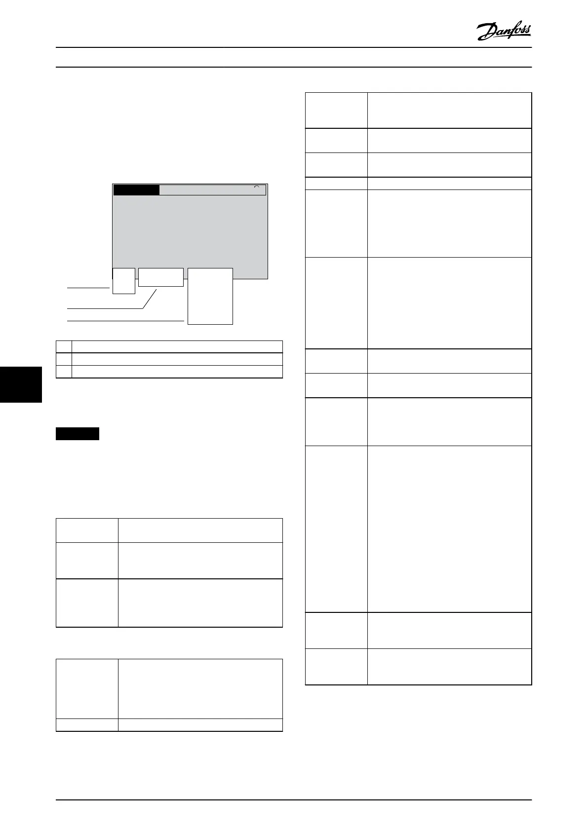
9.3 Status Messages
When the drive is in status mode, status messages
automatically appear in the lowest line of the LCP display.
Refer to Illustration 9.2. Status messages are dened in
Table 9.1 – Table 9.3.
Status
799RPM 7.83A 36.4kW
0.000
53.2%
1(1)
Auto
Hand
O
Remote
Local
Ramping
Stop
Running
Jogging
.
.
.
Stand-by
130BB037.11
1
2
3
1 Where the stop/start command originates. Refer to Table 9.1.
2 Where the speed control originates. Refer to Table 9.2.
3 Provides the drive status. Refer to Table 9.3.
Illustration 9.2 Status Display
NOTICE
In auto/remote mode, the drive requires external
commands to execute functions.
Table 9.1 to Table 9.3 dene the meaning of the shown
status messages.
O The drive does not react to any control signal
until [Auto On] or [Hand On] is pressed.
Auto The start/stop commands are sent via the
control terminals and/or the serial communi-
cation.
Hand The navigation keys on the LCP can be used
to control the drive. Stop commands, reset,
reversing, DC brake, and other signals applied
to the control terminals override local control.
Table 9.1 Operating Mode
Remote The speed reference is given from
•
External signals.
•
Serial communication.
•
Internal preset references.
Local The drive uses reference values from the LCP.
Table 9.2 Reference Site
AC brake AC brake was selected in parameter 2-10 Brake
Function. The AC brake overmagnetizes the
motor to achieve a controlled slow down.
AMA nish OK Automatic motor adaptation (AMA) was
carried out successfully.
AMA ready AMA is ready to start. To start, press [Hand
On].
AMA running AMA process is in progress.
Coast
•
[2] Coast inverse was selected as a function
for a digital input (parameter group 5-1*
Digital Inputs). The corresponding terminal
is not connected.
•
Coast activated by serial communication.
Ctrl. ramp-down [1] Ctrl. ramp-down was selected in
parameter 14-10 Mains Failure.
•
The mains voltage is below the value set
in parameter 14-11 Mains Voltage at Mains
Fault at mains fault.
•
The drive ramps down the motor using a
controlled ramp down.
Current high The drive output current is above the limit set
in parameter 4-51 Warning Current High.
Current low The drive output current is below the limit set
in parameter 4-52 Warning Speed Low.
DC hold DC hold is selected in parameter 1-80 Function
at Stop and a stop command is active. The
motor is held by a DC current set in
parameter 2-00 DC Hold Current.
DC stop The motor is held with a DC current
(parameter 2-01 DC Brake Current) for a
specied time (parameter 2-02 DC Braking
Time).
•
DC brake is activated in parameter 2-03 DC
Brake Cut In Speed [RPM] and a stop
command is active.
•
DC brake (inverse) is selected as a function
for a digital input (parameter group 5-1*
Digital Inputs). The corresponding terminal
is not active.
•
The DC brake is activated via serial
communication.
Feedback high The sum of all active feedbacks is above the
feedback limit set in parameter 4-57 Warning
Feedback High.
Feedback low The sum of all active feedbacks is below the
feedback limit set in parameter 4-56 Warning
Feedback Low.
Maintenance, Diagnostics, a... VLT® AutomationDrive FC 361
44 Danfoss A/S © 06/2018 All rights reserved. MG06I102
99

 Loading...


