4 Mechanical Installation
4.1 Items Supplied
Items supplied may vary according to product congu-
ration.
•
Make sure the items supplied and the information
on the nameplate correspond to the order conr-
mation.
•
Check the packaging and the drive visually for
damage caused by inappropriate handling during
shipment. File any claim for damage with the
carrier. Retain damaged parts for clarication.
OUT: 3x0-Vin 0-590Hz 212/190 A
IN: 3x380-480 V 50/60Hz 204/183 A
110 kW / 150 HP, High Overload
OUT: 3x0-Vir. 0-590Hz 260/240 A
132 kW / 200 HP, Normal Overload
VLT
T/C: FC-361N132T4E20H2RXCXXXSXXXXAXBX
P/N: 136G8270 S/N:
123456H123
R
AutomationDrive
www.danfoss.com
e30bg567.10
IN: 3x380-480V 50/60Hz 251/231 A
ASSEMBLED IN USA
Max Tamb. 55
C/131
F w/Output Current Derating
CHASSIS/IP20 Tamb. 45 C/113 F
CAUTION - ATTENTION:
Stored charge, wait 20 min.
Charge residuelle, attendez 20 min.
See manual for special condition / mains fuse
Voir manuel de conditions speciales / fusibles
WARNING - AVERTISSEMENT:
`
`
1
2
3
4
5
6
Danfoss A/S
6340 Nordborg
Denmark
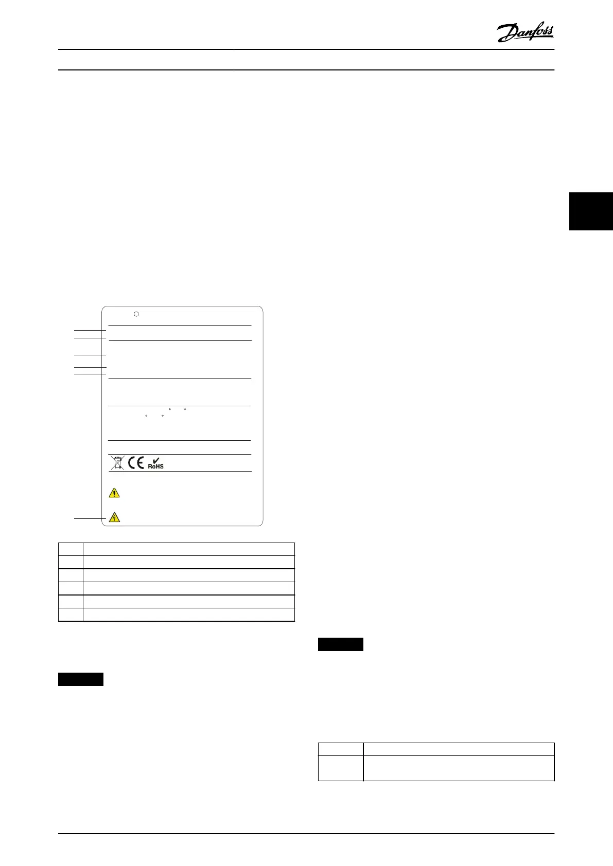
1 Type code
2 Part number and serial number
3 Power rating
4 Input voltage, frequency, and current
5 Output voltage, frequency, and current
6 Discharge time
Illustration 4.1 Example Nameplate for Drive Only (J8–J9)
NOTICE
LOSS OF WARRANTY
Do not remove the nameplate from the drive. Removing
the nameplate can result in loss of warranty.
4.2 Tools Needed
Receiving/unloading
•
I-beam and hooks rated to lift the weight of the
drive. Refer to chapter 3.2 Power Ratings, Weights,
and Dimensions.
•
Crane or other lifting aid to place the unit into
position.
Installation
•
Drill with 10 mm (0.39 in) or 12 mm (0.47 in) drill
bits.
•
Tape measurer.
•
Various sizes of Phillips and at bladed
screwdrivers.
•
Wrench with relevant metric sockets (7–17 mm/
0.28–0.67 in).
•
Wrench extensions.
•
Torx drives (T25 and T50).
•
Sheet metal punch for conduits or cable glands.
•
I-beam and hooks to lift the weight of the drive.
Refer to chapter 3.2 Power Ratings, Weights, and
Dimensions.
•
Crane or other lifting aid to place the drive onto
pedestal and into position.
4.3
Storage
Store the drive in a dry location. Keep the equipment
sealed in its packaging until installation. Refer to
chapter 10.4 Ambient Conditions for recommended ambient
temperature.
Periodic forming (capacitor charging) is not necessary
during storage unless storage exceeds 12 months.
4.4
Operating Environment
NOTICE
In environments with airborne liquids, particles, or
corrosive gases, ensure that the IP/type rating of the
equipment matches the installation environment. Failure
to meet requirements for ambient conditions can reduce
the lifetime of the drive. Ensure that requirements for air
humidity, temperature, and altitude are met.
Voltage [V] Altitude restrictions
380–480 At altitudes above 3000 m (9842 ft), contact
Danfoss regarding PELV.
Table 4.1 Installation at High Altitudes
Mechanical Installation Operating Guide
MG06I102 Danfoss A/S © 06/2018 All rights reserved. 13
4 4
 Loading...


