5.8.5 Conguring RS485 Serial
Communication
RS485 is a 2-wire bus interface compatible with multi-drop
network topology, and it contains the following features:
•
Either Danfoss FC or Modbus RTU communication
protocol, which are internal to the drive, can be
used.
•
Functions can be programmed remotely using
the protocol software and RS485 connection or in
parameter group 8-** Communications and
Options.
•
Selecting a specic communication protocol
changes various default parameter settings to
match the specications of the protocol, making
more protocol-specic parameters available.
•
Option cards for the drive are available to provide
more communication protocols. See the option
card documentation for installation and operation
instructions.
•
A switch (BUS TER) is provided on the control
card for bus termination resistance. See
Illustration 5.16.
For basic serial communication set-up, perform the
following steps:
1. Connect RS485 serial communication wiring to
terminals (+)68 and (-)69.
1a Use shielded serial communication cable
(recommended).
1b See chapter 5.4 Connecting to Ground for
proper grounding.
2. Select the following parameter settings:
2a Protocol type in parameter 8-30 Protocol.
2b Drive address in parameter 8-31 Address.
2c Baud rate in parameter 8-32 Baud Rate.
Illustration 5.15 Serial Communication Wiring Diagram
5.8.6 Selecting Voltage/Current Input
Signal
The analog input terminals 53 and 54 allow setting of
input signal to voltage (0–10 V) or current (0/4–20 mA).
Default parameter setting:
•
Terminal 53: Speed reference signal in open loop
(see parameter 16-61 Terminal 53 Switch Setting).
•
Terminal 54: Feedback signal in closed loop (see
parameter 16-63 Terminal 54 Switch Setting).
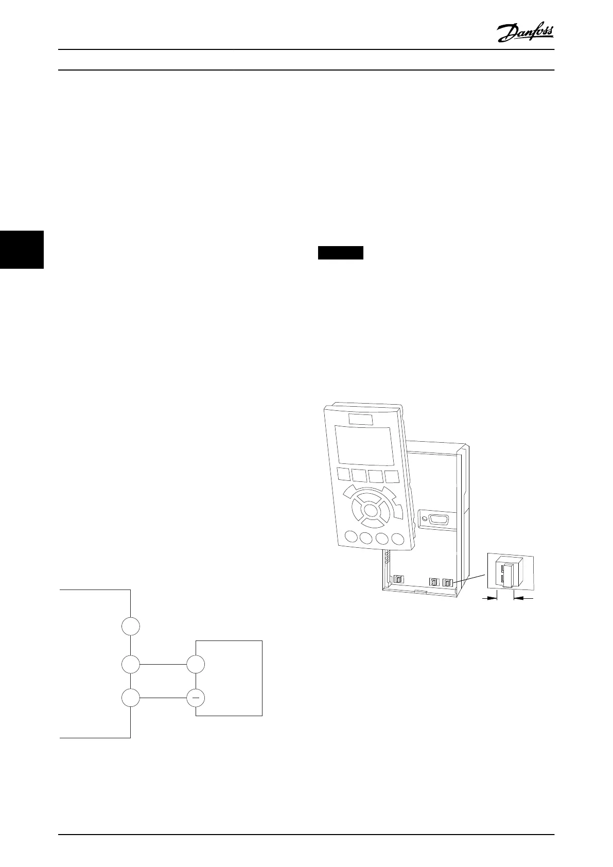
NOTICE
Disconnect power to the drive before changing switch
positions.
1. Remove the LCP (local control panel).
See chapter 3.7 LCP Menus.
2. Remove any optional equipment covering the
switches.
3. Set switches A53 and A54 to select the signal
type (U = voltage, I = current).
BUS TER.
OFF-ON
A53 A54
U- I U- I
Illustration 5.16 Location of Terminal 53 and 54 Switches
Electrical Installation VLT® AutomationDrive FC 361
34 Danfoss A/S © 06/2018 All rights reserved. MG06I102
55

 Loading...


