Digital input/output terminals
Terminal Parameter Default
setting
Description
18 Parameter 5-10
Terminal 18
Digital Input
[8] Start Digital inputs.
19 Parameter 5-11
Terminal 19
Digital Input
[10]
Reversing
32 Parameter 5-14
Terminal 32
Digital Input
[0] No
operation
33 Parameter 5-15
Terminal 33
Digital Input
[0] No
operation
27 Parameter 5-12
Terminal 27
Digital Input
[2] Coast
inverse
For digital input or
output. Default
setting is input.
29 Parameter 5-13
Terminal 29
Digital Input
[14] JOG
20 – – Common for digital
inputs and 0 V
potential for 24 V
supply.
Table 5.2 Digital Input/Output Terminal Descriptions
Analog input/output terminals
Terminal Parameter Default
setting
Description
39 – – Common for analog
output.
42 Parameter 6-50
Terminal 42
Output
[0] No
operation
Programmable analog
output. 0–20 mA or
4–20 mA at a
maximum of 500 Ω.
50 – +10 V DC 10 V DC analog
supply voltage for
potentiometer or
thermistor. 15 mA
maximum.
53 Parameter
group 6-1*
Analog Input 1
Reference Analog input. For
voltage or current.
Switches A53 and
A54 select mA or V.
54 Parameter
group 6-2*
Analog Input 2
Feedback
55 – – Common for analog
input.
Table 5.3 Analog Input/Output Terminal Descriptions
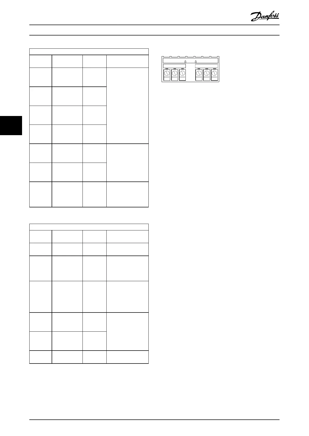
Relay terminals:
RELAY 1 RELAY 2
01 02 03 04 05 06
130BF156.10
Illustration 5.12 Relay 1 and Relay 2 Terminals
•
Relay 1 and relay 2. The location of the outputs
depends on the drive conguration. See
chapter 3.5 View of Control Shelf.
•
Terminals on built-in optional equipment. See the
manual provided with the equipment option.
Electrical Installation VLT® AutomationDrive FC 361
32 Danfoss A/S © 06/2018 All rights reserved. MG06I102
55
 Loading...


