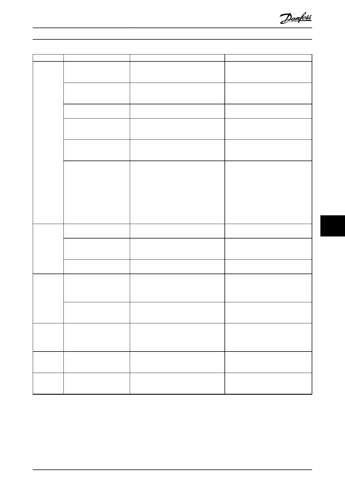
Symptom Possible cause Test Solution
Motor not
running
Service switch open or missing
motor connection.
Check if the motor is connected and the
connection is not interrupted by a service
switch or other device.
Connect the motor and check the service
switch.
No mains power with 24 V DC
option card.
If the display is functioning, but there is no
output, check that mains power is applied to
the AC drive.
Apply mains power.
LCP Stop. Check if [O] has been pressed. Press [Auto On] or [Hand On] (depending
on operating mode).
Missing start signal (Standby). Check parameter 5-10 Terminal 18 Digital Input
for correct setting for terminal 18. Use default
setting.
Apply a valid start signal.
Motor coast signal active
(Coasting).
Check parameter 5-12 Terminal 27 Digital Input
for correct setting for terminal 27 (use default
setting).
Apply 24 V on terminal 27 or program
this terminal to [0] No operation.
Wrong reference signal source. Check reference signal:
•
Local.
•
Remote or bus reference?
•
Preset reference active?
•
Terminal connection correct?
•
Scaling of terminals correct?
•
Reference signal available?
Program correct settings. Check
parameter 3-13 Reference Site. Set preset
reference active in parameter group 3-1*
References. Check for correct wiring. Check
scaling of terminals. Check reference
signal.
Motor
running in
wrong
direction
Motor rotation limit. Check that parameter 4-10 Motor Speed
Direction is programmed correctly.
Program correct settings.
Active reversing signal. Check if a reversing command is programmed
for the terminal in parameter group 5-1*
Digital inputs.
Deactivate reversing signal.
Wrong motor phase
connection.
– See chapter 7.3.1 Warning - Motor Start.
Motor is not
reaching
maximum
speed
Frequency limits set wrong. Check output limits in parameter 4-13 Motor
Speed High Limit [RPM], parameter 4-14 Motor
Speed High Limit [Hz], and parameter 4-19 Max
Output Frequency
Program correct limits.
Reference input signal not
scaled correctly.
Check reference input signal scaling in
parameter group 6-0* Analog I/O mode and
parameter group 3-1* References.
Program correct settings.
Motor speed
unstable
Possible incorrect parameter
settings.
Check the settings of all motor parameters,
including all motor compensation settings.
For closed-loop operation, check PID settings.
Check settings in parameter group 1-6*
Load Depen. Setting. For closed-loop
operation, check settings in parameter
group 20-0* Feedback.
Motor runs
rough
Possible overmagnetization. Check for incorrect motor settings in all
motor parameters.
Check motor settings in parameter groups
1-2* Motor data, 1-3* Adv Motor Data, and
1-5* Load Indep. Setting.
Motor does
not brake
Possible incorrect settings in
the brake parameters. Ramp-
down times may be too short.
Check brake parameters. Check ramp time
settings.
Check parameter groups 2-0* DC Brake and
3-0* Reference Limits.
Maintenance, Diagnostics, a... Operating Guide
MG06I102 Danfoss A/S © 06/2018 All rights reserved. 55
9 9
 Loading...


