130BP075.10
OR
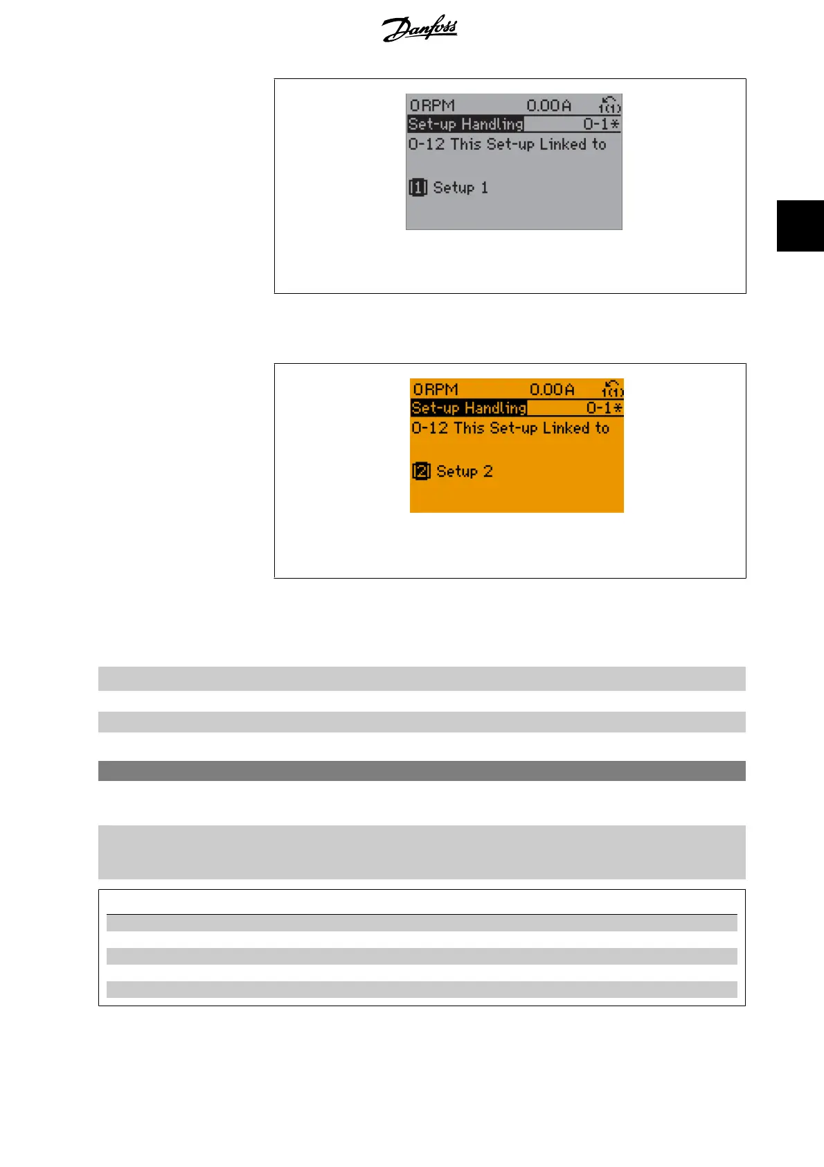
2. While still in Set-up 1, using par. 0-50, copy Set-up 1 to Set-up 2. Then set par. 0-12 to
Set-up 2
[2]. This
will start the linking process.
130BP076.10
After the link is complete, par. 0-13
Readout: Linked Set-ups
will read {1,2} to indicate that all ‘not changeable
during operation’ parameters are now the same in Set-up 1 and Set-up 2. If there are changes to a ‘not change-
able during operation’ parameter, e.g. par 1-30
Stator Resistance (rs)
, in Set-up 2, they will also be changed
automatically in Set-up 1. A switch between Set-up 1 and Set-up 2 during operation is now possible.
[1]
*
Set-up 1
[2] Set-up 2
[3] Set-up 3
[4] Set-up 4
0-13 Readout: Linked Set-ups
Array [5]
0
*
[0 - 255]
View a list of all the set-ups linked by means of par. 0-12
This Set-up Linked to
. The parameter has one index
for each parameter set-up. The parameter value displayed for each index represents which setups are linked to
that parameter setup.
Index
LCP value
0 {0}
1 {1,2}
2 {1,2}
3{3}
4 {4}
Table 3.1: Example: Set-up 1 and Set-up 2 are linked
VLT
®
HVAC Drive Programming Guide 3. Parameter Description
MG.11.C5.02 - VLT
®
is a registered Danfoss trademark
27
3
 Loading...


