EasyManuals Logo

Danfoss vlt FC 102 Installation Guide

Danfoss vlt FC 102
84 pages
To Next Page IconTo Next Page
To Previous Page IconTo Previous Page
Page #75 background imageLoading...
Page #75 background image
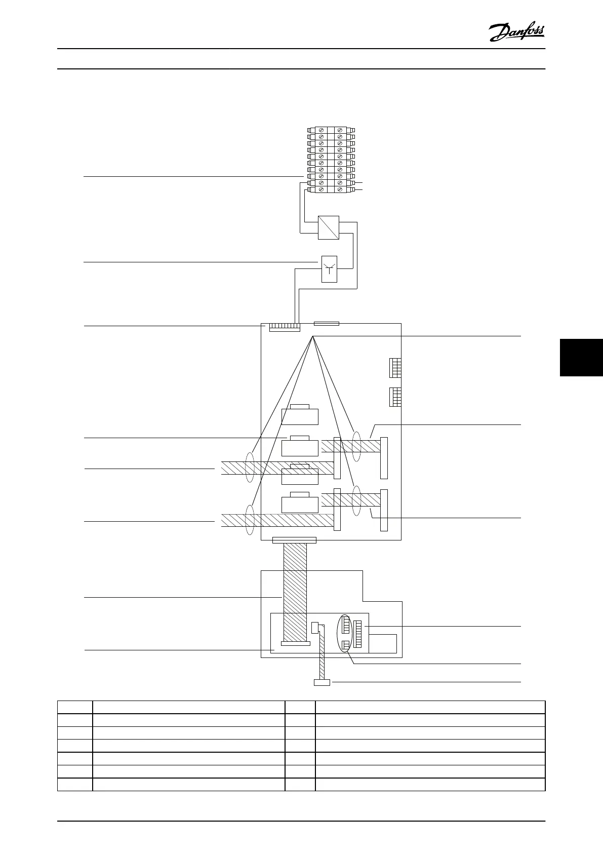
8.3.6 Control Shelf Connections
130BE739.10
FC–X02
1
1
1
1
1
1 2 3 4 5 6 7 8 9 10
2
2
3455 6
6
1
2
5
6
123456
2
2
2
43 44
4344
43
44
1
2
43
44
1
2
43
44
1
2
43
44
FK100
MK100
MK115
MK106
MK111
MK112 MK114
MK113
MK107
MK108
MK109
MK110
FK101
INV1 INV2 INV3 INV4
L
AC
DC
N
230V
12
9
10
11
13 14
1
2 5
3
4
6
7
8
1 LCP cradle 8 Terminal block
2 Ribbon cable from LCP to MDCIC 9 Cable to remote-mounted LCP
3 44-pin cable to the drive module 1 (at MK 111) 10 Analog I/O terminals
4 44-pin cable to the drive module 3 (at MK 113) 11 Digital input terminals
5 Current scaling card 12 44-pin cable to the drive module 2 (at MK 112)
6 STO connector 13 44-pin cable to the drive module 4 (at MK 114)
7 STO relay 14 Ferrite cores
Illustration 8.6 Control Shelf Connections
Appendix Installation Guide
MG37K302 Danfoss A/S © 08/2017 All rights reserved. 73
8 8

Table of Contents

Other manuals for Danfoss vlt FC 102

Questions and Answers:

Question and Answer IconNeed help?

Do you have a question about the Danfoss vlt FC 102 and is the answer not in the manual?

Danfoss vlt FC 102 Specifications

General IconGeneral
CategoryDC Drives
ModelDanfoss VLT FC 102
Output voltage range0 to rated motor voltage
Power range0.37 kW to 200 kW
Communication interfacesRS-485
Protection featuresOvervoltage, undervoltage, overcurrent, short circuit, earth fault, overtemperature, motor thermal protection
Cooling methodAir-cooled
Enclosure ratingIP20, IP21, IP55 (depending on model)
ApprovalsCE, UL, cUL

Related product manuals