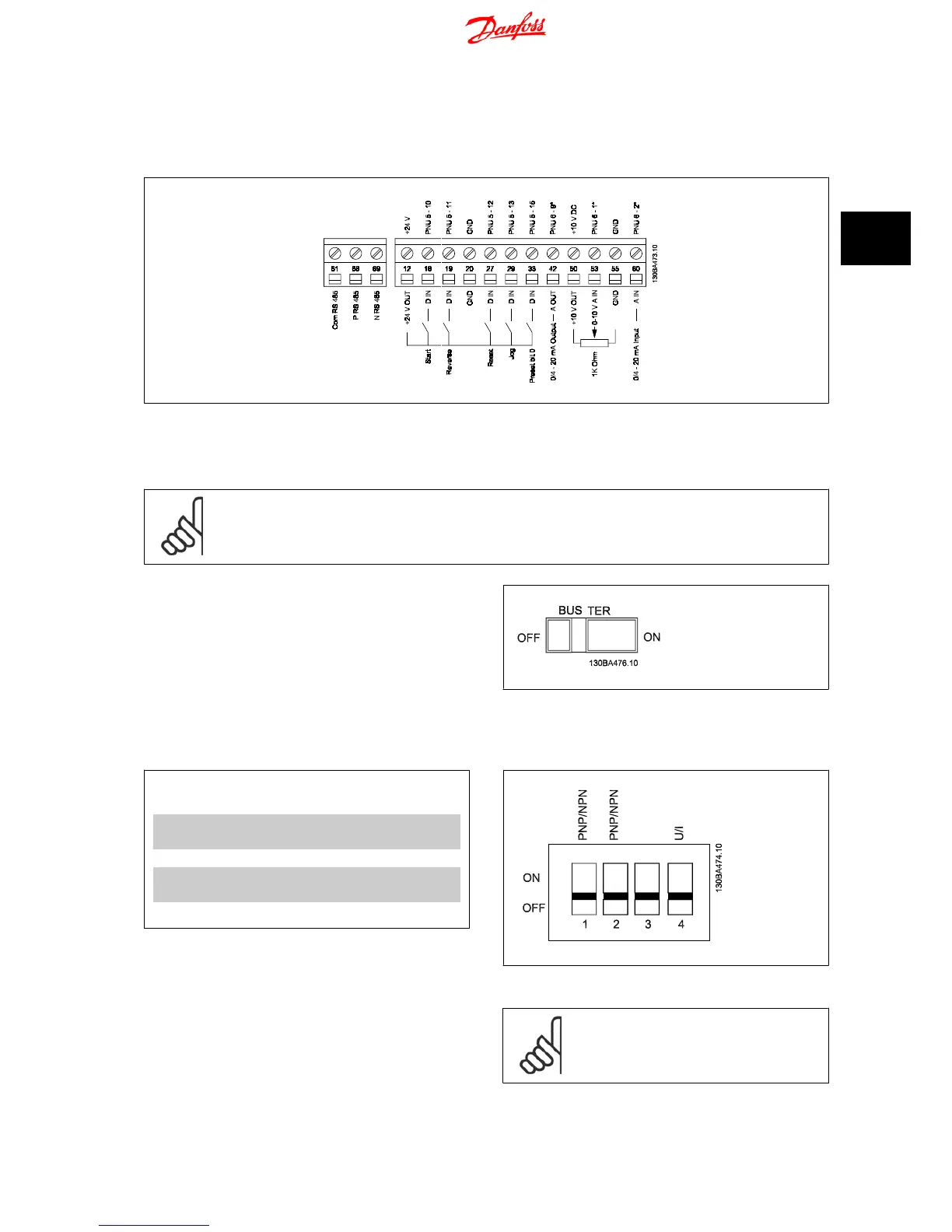
3.4.2 Connecting to Control Terminals
This illustration shows all control terminals of the frequency converter. Applying Start (term. 18) and an analog reference (term. 53 or 60) make the
frequency converter run.
Illustration 3.7: Overview of control terminals in PNP-configuration and factory setting.
3.5 Switches
NB!
Do not operate switches with power on the frequency converter.
Bus termination:
Switch
BUS TER
pos. ON terminates the RS485 port, terminals 68, 69.
See power circuit drawing.
Default setting = Off.
Illustration 3.8: S640 Bus termination.
S200 Switches 1-4:
Switch 1: *OFF = PNP terminals 29
ON = NPN terminals 29
Switch 2: *OFF = PNP terminal 18, 19, 27 and 33
ON = NPN terminal 18, 19, 27 and 33
Switch 3: No function
Switch 4: *OFF = Terminal 53 0 - 10 V
ON = Terminal 53 0/4 - 20 mA
* = default setting
Table 3.5: Settings for S200 Switches 1-4
Illustration 3.9: S200 Switches 1-4.
NB!
Parameter 6-19 must be set according to Switch 4 po-
sition.
VLT
®
Micro Drive FC 51 Operating Instructions 3 Electrical Installation
MG.02.A4.02 - VLT
®
is a registered Danfoss trademark
15
3

 Loading...


