1.
2.
3.
4.
3 Installation
3.1 Before Commencing Repair Work
Procedure
Disconnect the VLT® Micro DriveFC 51 from mains (and external DC supply, if present).
Wait for 4 minutes (M1, M2, and M3) and 15 minutes (M4 and M5) for discharge of the DC-link.
Disconnect the DC bus terminals and the brake terminals (if present).
Remove the motor cable.
3.2 Side-by-side Installation
The drive can be mounted side by side for IP20 rating units and requires 100 mm (3.9 in) clearance above and below for cooling.
Refer to chapter Specications for details on environmental ratings of the drive.
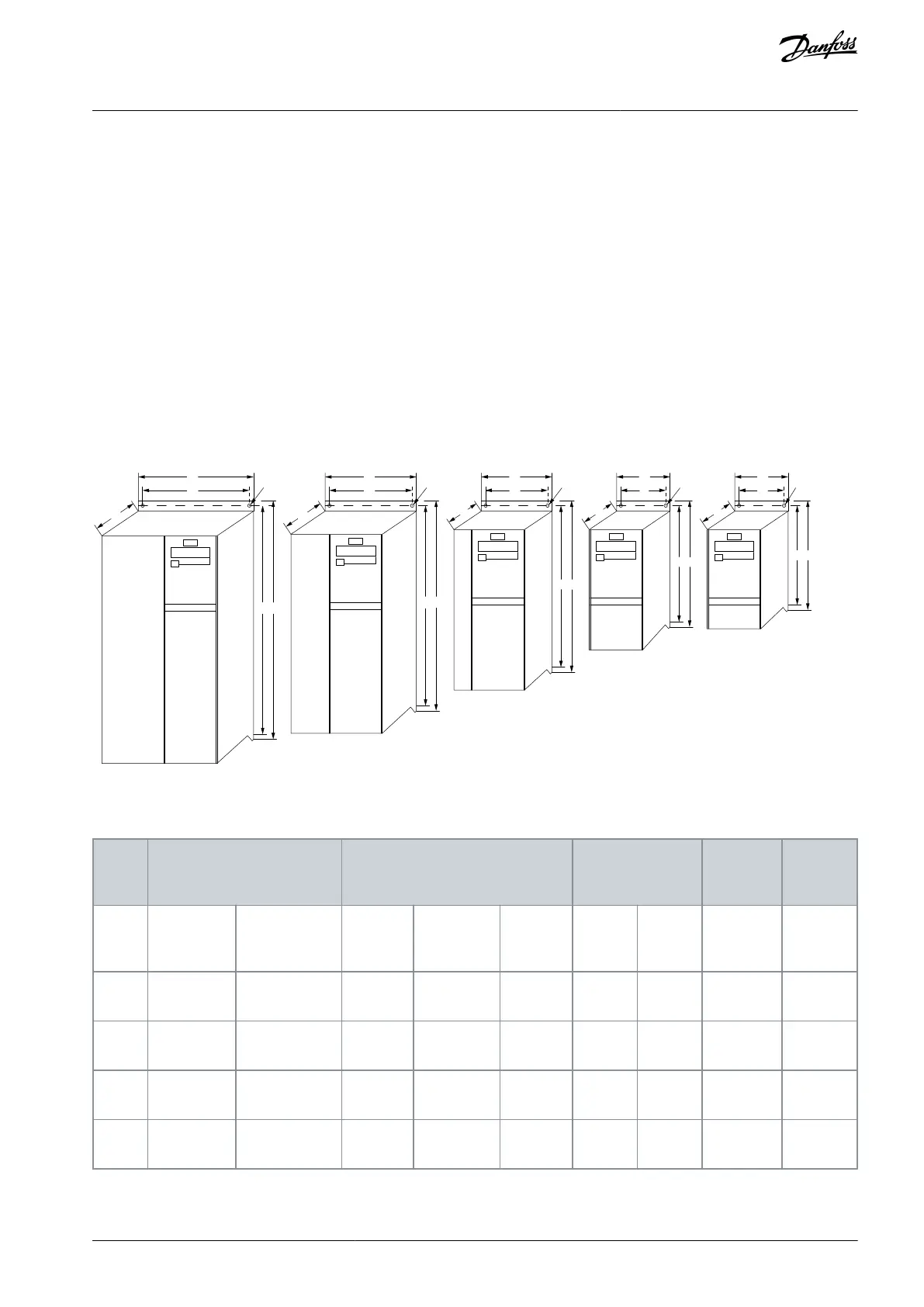
3.3 Mechanical Dimensions
A template for drilling is found on the ap of the packaging.
M4
M3
M2
M1
Ø 7mm Ø 5.5mm Ø 4.5mm
e30bb321.11
Ø 4.5mm
Illustration 1: Mechanical Dimensions
Table 2: Mechanical Dimensions
A (including
decoupling
plate)
AQ348848915086en-000101 / 130R0943 | 9Danfoss A/S © 2020.09
Installation
VLT® Micro Drive FC 51
Operating Guide
 Loading...


