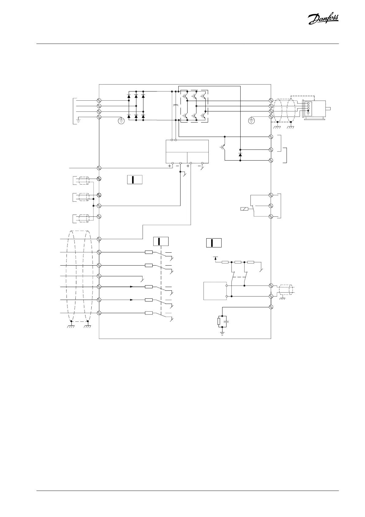
3.8 Power Circuit
e30ba242.18
+ 10 V DC
0-10 V DC -
0/4-20 mA
0/4-20 mA
Analog output
0/4-20 mA
50 (+10 V OUT)
53 (A IN)
60 (A IN)
55 (COM A IN/OUT)
42 (A OUT)
12 (+24 V OUT)
18 (D IN)
19 (D IN)
20 (COM D IN)
27 (D IN)
29 (D IN)
33 (D IN)
S200
S200
ON (NPN)
OFF (PNP)
24 V
0 V
(NPN)
(PNP)
24 V
0 V
(NPN)
(PNP)
24 V
0 V
(NPN)
(PNP)
24 V
0 V
(NPN)
(PNP)
24 V
0 V
(NPN)
(PNP)
RS485
interface
(N RS485) 69
(P RS485) 68
(COM RS485) 61
RS485
(PNP) = Source
(NPN) = Sink
S801
0 V
S640
ON = Terminated
OFF = Open
Relay 1
03
02
01
240 V AC, 2 A
Brake
resistor
1)
DC bus
Motor
UDC-
UDC+/BR+
10 V DC 24 V DC
5 V
3 phase
power
input
L1/L
L2
L3/N
PE
4
ON
1 2
ON
1 2
ON
Illustration 6: Diagram Showing all Electrical Terminals
1) Brakes (BR+ and BR-) are not applicable for enclosure size M1.
For information about brake resistors, see VLT® Brake Resistor MCE 101 Design Guide.
Improved power factor and EMC performance can be achieved by installing optional Danfoss line lters.
Danfoss power lters can also be used for load sharing. For more information about load sharing, see VLT® Micro DriveFC 51 Load
Sharing application note.
3.9 Load Sharing/Brake
Use 6.3 mm (0.25 in) insulated Faston plugs designed for high voltage for DC (load sharing and brake).
Contact Danfoss or see Load sharing instruction VLT® 5000 for load sharing and VLT® 2800/5000/5000 FLUX/FCD 300 Brake for brake.
Load sharing
Connect terminals -UDC and +UDC/+BR.
Brake
Connect terminals -BR and +UDC/+BR (not applicable for enclosure size M1).
AQ348848915086en-000101 / 130R0943 | 15Danfoss A/S © 2020.09
Installation
VLT® Micro Drive FC 51
Operating Guide

 Loading...


